Overview
Manuals
Use Cases
Configuration & Programming
Features:
- Functions as a remote I/O scanner module within the SLC 500 series
- This module facilitates connections between I/O adapters and controllers
- Ensuring compatibility for distributed controller applications and offering robust noise immunity
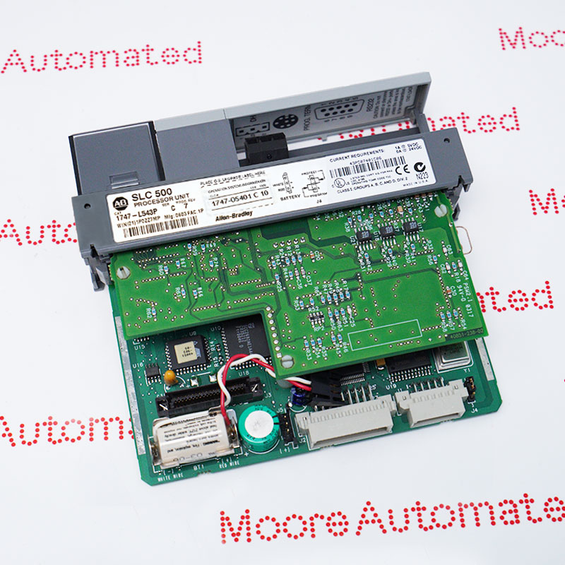
Allen Bradley's 1747-SN Remote I/O Scan Module is a key component of the SLC 500 Series. This module is designed to simplify the connection between the I/O adapter and the controller, thereby enhancing the flexibility of distributed controller applications. It supports normal and complementary modes, allowing up to 16 devices to connect in normal mode and up to 32 devices in complementary mode, depending on system requirements, thus improving application flexibility.
The module supports RIO cables up to 3050 meters long, which is particularly advantageous in large-scale applications where I/O devices are located far from the controller. Furthermore, the module features a noise-resistant design, ensuring stability and reliability even in environments susceptible to electrical noise. Its backplane current is 600 mA (5 volts), providing moderate power consumption.
The 1747-SN Allen Bradley Remote I/O Scanner Module may still be available for purchase and support from Moore Automated Company beyond End-Of-Life (EOL) by the manufacturer (OEM).
Allen Bradley 1747-SN Remote I/O Scanner Module manual(Datasheets), Link
Important Notice: Other accessories, manuals, cables, calibration data, software, etc. are not included with this equipment unless listed in the above stock item description. All prices are shown in USD.
1. Plant-wide Distributed I/O Infrastructure
Multi-rack Expansion Cabinet: In large manufacturing plants, connecting individual sensor cables to a central control room is extremely costly. Therefore, the 1747-SN can be used to coordinate remote racks containing 1747-ASB adapters. This allows the SLC processor to scan discrete and analog I/O points up to 3,000 meters away.
Modular Field Access Integration: It acts as the RIO network master, collecting real-time process data from remote, localized terminal blocks, such as 1794 Flex I/O or 1797 EX-I/O deployed directly near field instruments.
2. Multi-Node Motor Control and Drive System
Variable Frequency Drive (VFD) Array: This module is widely used in heavy-duty material handling equipment to manage speed references and run/stop statuses of traditional Allen-Bradley 1336 Plus, 1305, or PowerFlex VFD arrays equipped with RIO communication adapters.
Motor Control Center (MCC): It provides deterministic sequential control of multiple low-voltage motor starters, contactors, and overload relays through a unified control room interface, eliminating the need for dense wiring harnesses.
3. Long-Distance Heavy Industrial Environments:
Automotive Assembly and Conveying Circuits: Deployed in large paint shops, body shops, and sorting conveyors for synchronizing emergency stop actuators, part travel limits, and safety interlocks between different local work units.
Wastewater Treatment and Remote Pumping: Used to connect a central control station to water clarification tanks, chemical metering tanks, and remote lifting stations distributed over a wide geographical area.
Material Conveying and Silo Storage: Used in grain silos, coal terminals, and cement plants for connecting hazard monitoring sensors (e.g., belt misalignment or bearing temperature transmitters) on long-distance conveying structures.
1. Hardware DIP Switch Settings (Baud Rate): Before inserting the module into the SLC 500 chassis, its onboard physical DIP switches must be configured to fully match the baud rate of all remote adapters (e.g., 1747-ASB or 1794-ASB) on the Blue Pipe network link.
Physical Interlock Requirement: This module only reads switch changes during cold starts. Always power off the chassis before changing the DIP switch position.
Baud Rate vs. Distance: Select 57.6 kbps (for lines up to 3,048 meters), 115.2 kbps (for lines up to 1,524 meters), or 230.4 kbps (for lines up to 762 meters). Ensure a matching terminating resistor (82Ω or 150Ω) is installed between Line 1 and Line 2 at the physical end of the daisy chain.
2. Software Configuration (G-File Settings) The G-file (Scanner Configuration Data File) tells the 1747-SN which logical racks, starting groups, and partial sizes (full rack, half rack, or quarter rack layout) on the network link to actively poll:
Open your offline project in RSLogix 500 and double-click "I/O Configuration". Drag and drop the correct 1747-SN scanner series into its physical slot. Click "Advanced Configuration" (Adv Config) and then select "Edit 'G' Data". Map your remote chassis by matching the logical rack number and size to the field hardware settings (e.g., set rack 0 to "Full Rack" or rack 1 to "Half Rack").