Overview
Manuals
Principle
Features:
- PACSystems RX3i and Series 90-30
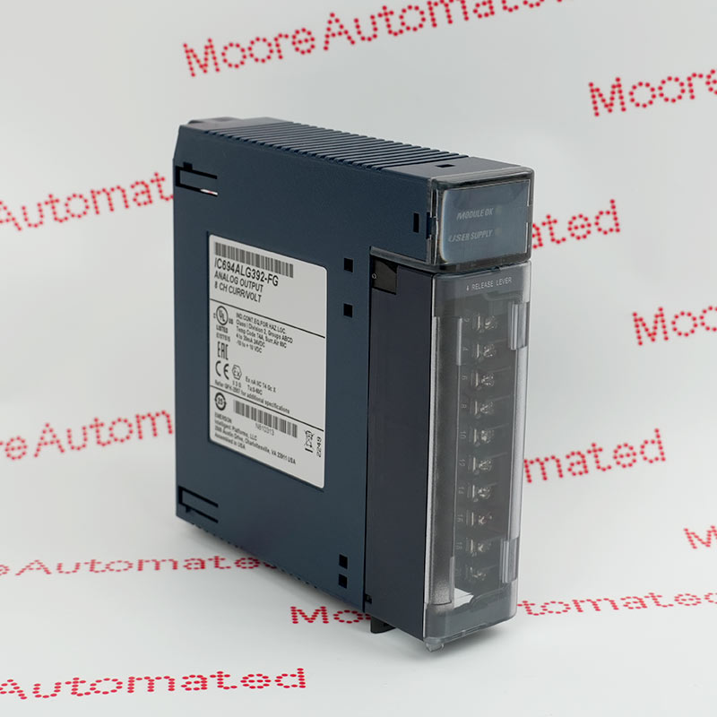
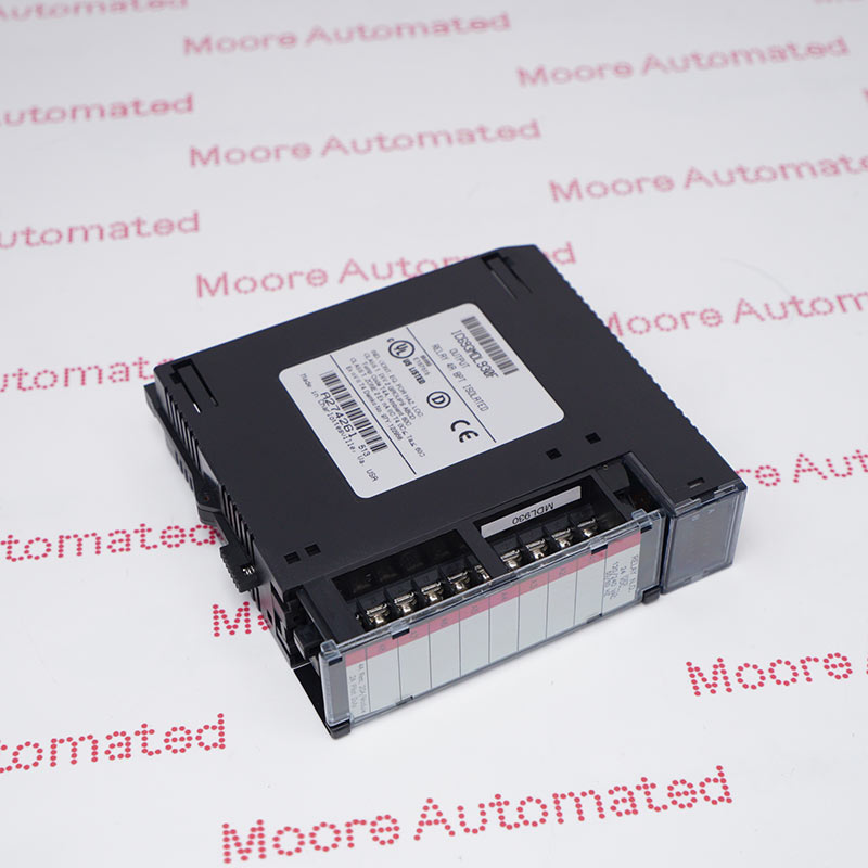
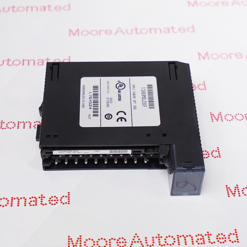
- Output Module, Isolated Relay, NO, 4 Amp, 8 Point
- provide eight normally open relay circuits for controlling output loads
The MDL930 Series 90*-30 and PACSystems* 4 Amp Isolated Relay Output modules, provide eight normally open relay circuits for controlling output loads. The output switching capacity of each circuit is 4 Amps. Each output point is isolated from the other points, and each point has a separate common power output terminal. The relay outputs can control a wide range of output devices, such as motor starters, solenoids, and indicators.
Individual numbered LEDs display the ON/OFF status of each output point. There are no fuses on this module. The red bands on the label show that MDL930 is a high-voltage module. This module can be installed in any I/O slot in a Series 90-30 or RX3i system. The user must supply the AC or DC power to operate the field devices connected to this module.
The IC694MDL930 GENERAL ELECTRIC Output Module may still be available for purchase and support from Moore Automated Company beyond End-Of-Life (EOL) by the manufacturer (OEM).
GENERAL ELECTRIC IC694MDL930 Output Module datasheet(manual), Link
Important Notice: Other accessories, manuals, cables, calibration data, software, etc. are not included with this equipment unless listed in the above stock item description. All prices are shown in USD.
This product is intended for use with the Series 90-30 or RX3i system. Its components are considered open equipment [having live electrical parts that may be accessible to users] and must be installed in an ultimate enclosure that is manufactured to provide safety. As a minimum, the enclosure shall provide a degree of protection against solid objects up to 12mm (e.g. fingers). This equates to a NEMA/UL Type 1 enclosure or an IP20 rating (IEC60529) providing at least a pollution degree 2 environment.