

Registered Address: 32D Floor Guomao Building, No.388, Hubin South Road, Siming District, Xiamen,Fujian, China
ISO 9001:2015 Certified
Our quality management system covers sourcing,testing and dispatch

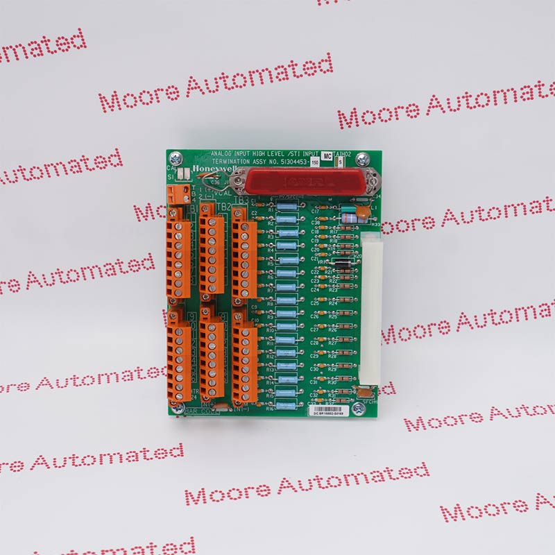
CC-TFB412 51308311-275 is a Honeywell Experion Series C coated redundant Fieldbus Input/Output Termination Assembly for four Foundation Fieldbus networks. The reviewed Honeywell source pairs it with CC-PFB401 and distinguishes it from the nonredundant CC-TFB402. It provides the physical module mounting, power and network/field-wiring connections; Fieldbus communication processing resides in the paired electronics module.
CC-TFB412 is the redundant coated Input/Output Termination Assembly for the Series C four-network Fieldbus interface. The reviewed Honeywell table pairs it with CC-PFB401 and identifies CC-TFB402 as the nonredundant IOTA. Honeywell lists 24 VDC load voltage, 0.196 A load current and four RJ-45 connections for the redundant execution, with external 24 VDC/350 mA total Foundation Fieldbus wiring context. These values describe the documented assembly and must be applied with the approved cabinet design.
The IOTA provides module mounting and the physical power, Ethernet and H1-link termination boundary. Fieldbus communication processing, link status and system diagnostics reside in the paired CC-PFB401 electronics and Experion configuration. Before replacement, record every H1 segment, shield, power conditioner, terminator, Ethernet cable and module position. Confirm the complete 51308311-275 marking, printed revision, fuse arrangement, hazardous-area requirements and controller release; do not substitute the nonredundant IOTA without an engineered architecture review.
Use CC-TFB412 with the approved Series C CC-PFB401 four-network Fieldbus electronic module and the documented controller release. Confirm redundant cabinet layout, module revision, firmware and Experion configuration before ordering. Verify that the replacement preserves both module paths, connector positions and every configured link assignment.
Record each Foundation Fieldbus segment, polarity, shield, power conditioner, terminator and external 24 VDC source before disconnection. Preserve separation, grounding and segment-current design; do not infer link health from continuity alone. Compare the completed wiring against the approved cabinet drawing before energizing any connected field device.
After installation, verify both module paths, Ethernet connections and all four H1 link states through authorized Experion diagnostics. Confirm device visibility, communication quality, alarms and redundancy transfer before returning the process to service. Record the tested path, connected devices, observed alarms and final link condition in the maintenance record.
The CC-TFB412 provides redundant physical mounting and termination for a CC-PFB401 four-network Fieldbus interface. Honeywell lists 24 VDC load voltage, 0.196 A load current, four RJ-45 connections for the redundant execution and external 24 VDC/350 mA total Fieldbus wiring context. Communication processing, link diagnostics and device data handling remain functions of the paired module and Experion configuration.
Photograph and label both module positions, Ethernet cables and every H1 segment before removal. Match the complete 51308311-275 marking and printed revision, inspect fuses/connectors, then restore the approved power-conditioning, grounding and termination design. Verify all four links, connected devices, alarms, communication quality and redundancy transfer with authorized system diagnostics before release.

Registered Address: 32D Floor Guomao Building, No.388, Hubin South Road, Siming District, Xiamen,Fujian, China
MooreAutomated.com is the official website and primary online platform operated by Moore Automation Limited. The website provides information about the company’s industrial automation parts sourcing services, product coverage and customer support. Moore Automation Limited operates as an independent supplier and is not an authorized distributor or representative of the manufacturers displayed on this website unless expressly stated.