

Registered Address: 32D Floor Guomao Building, No.388, Hubin South Road, Siming District, Xiamen,Fujian, China
ISO 9001:2015 Certified
Our quality management system covers sourcing,testing and dispatch

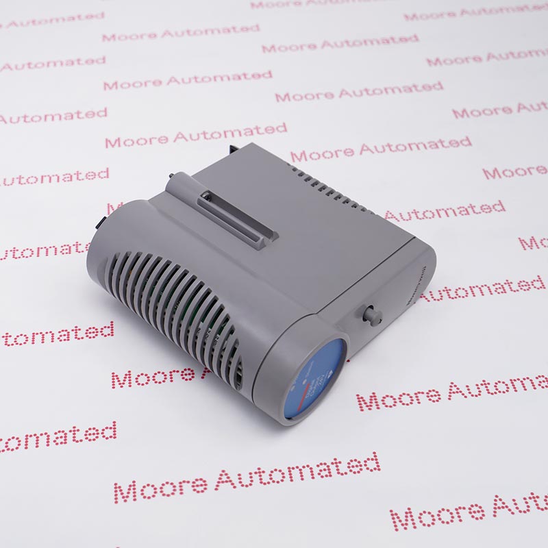
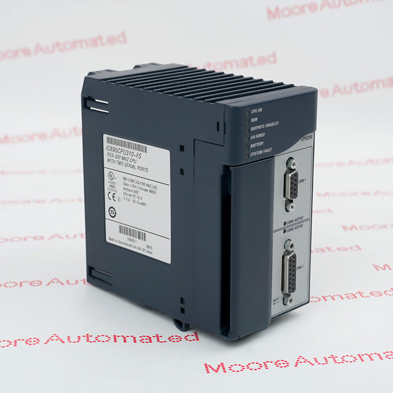
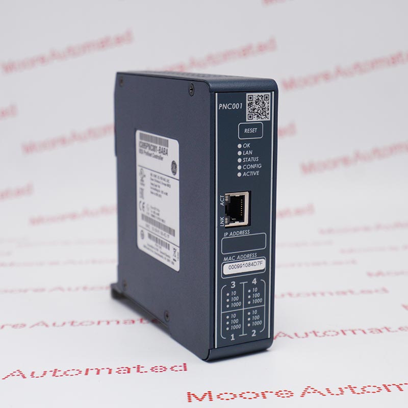
Honeywell lists DC-TDIL61 as an I/O Termination Assembly option for CC-PDIL51 low-voltage digital input and CC-PDIS51 sequence-of-events digital input in its Universal Marshalling Solution tables. It is terminal hardware, not the I/O electronics module. Confirm the paired module, field wiring and installed marshalling design before replacement.
Honeywell's November 2020 Universal Marshalling Solution Specification includes DC-TDIL61 in the IOTA column for two named I/O modules: CC-PDIL51 for low-voltage 24 V DC digital input and CC-PDIS51 for 24 V DC digital input sequence of events. The document's column structure separates terminal assemblies from I/O electronics. A DC-TDIL61 purchase therefore needs an assembly-level compatibility check, not an assumption that this terminal hardware performs digital filtering, optical isolation or event time stamping by itself. The two module types also serve different functions and should not be conflated.
Before replacement, record the complete DC-TDIL61 manufacturer label and revision, installed CC-PDIL51 or CC-PDIS51 electronics, cabinet position, terminal numbers, field supply and all connected circuits. Check the approved universal-marshalling and barrier design rather than borrowing compliance or entity figures printed for another device in the same Honeywell PDF. The existing page's 32-channel, 1000 VAC isolation, input impedance and filter-delay values are not independently attributed to DC-TDIL61 in the reviewed table. Follow manufacturer and site change-control instructions, then verify each affected digital input and SOE behavior where applicable before returning the assembly to service.
Honeywell lists DC-TDIL61 under IOTA, while the electronics appear in a separate I/O-module column. That distinction prevents channel count, optocoupler isolation or event-recording capability from being assigned to the termination assembly alone. The document pairs DC-TDIL61 with both CC-PDIL51 and CC-PDIS51 in a particular universal-marshalling context. Verify the exact installed companion module and manufacturer label rather than treating those two electronics functions as interchangeable.
The CC-PDIL51 row describes 24 V DC low-voltage digital input, and the CC-PDIS51 row describes 24 V DC sequence-of-events digital input. DC-TDIL61 appears as an IOTA option in both. That listing establishes a documented pairing, not permission to substitute any other TDIL hardware or ignore field-wiring differences. Compare the terminal drawing, field supply, barrier arrangement and site configuration against the approved design and current Honeywell release guidance.
The 2020 PDF includes technical limits for associated I/O and universal-marshalling barriers in nearby sections. Those figures must not be copied onto DC-TDIL61 without an exact IOTA specification. In particular, the reviewed rows do not state DC-TDIL61's independent 32-channel rating, galvanic isolation, filter delay or ON threshold. Verify such values for the complete module-plus-IOTA assembly in the correct manufacturer document before using them for procurement or design.
Identify DC-TDIL61 on the physical terminal assembly and determine whether the installed electronics are CC-PDIL51 or CC-PDIS51. Honeywell documents both in its compatibility tables but gives them different DI functions. Compare terminal numbering, field supply, cabling, barrier or isolator selection and the approved I/O configuration. Do not apply a neighboring module's 32-channel, impedance, optical-isolation or response-time figure to the bare IOTA without exact manufacturer support.
Preserve label and revision photographs, terminal assignments, loop drawings and baseline diagnostics before authorized work. Confirm the site-specific isolation and safety procedure; an IOTA compatibility table is not an online-exchange instruction. Install only the verified assembly, reconnect each conductor according to the approved drawing, and restore the associated I/O module configuration. Afterward test all affected digital inputs and, for a sequence-of-events installation, validate event detection and timing through the approved system test plan.

Registered Address: 32D Floor Guomao Building, No.388, Hubin South Road, Siming District, Xiamen,Fujian, China
MooreAutomated.com is the official website and primary online platform operated by Moore Automation Limited. The website provides information about the company’s industrial automation parts sourcing services, product coverage and customer support. Moore Automation Limited operates as an independent supplier and is not an authorized distributor or representative of the manufacturers displayed on this website unless expressly stated.