

Registered Address: 32D Floor Guomao Building, No.388, Hubin South Road, Siming District, Xiamen,Fujian, China
ISO 9001:2015 Certified
Our quality management system covers sourcing,testing and dispatch
MC-PPIX02 is a conformally coated Honeywell pulse input processor for the Process Manager I/O platform. Its eight channels acquire pulse-voltage or contact signals through the matched field termination assembly, providing rate and totalization data to the control system. The specified frequency range reaches 20 kHz under the stated waveform, filter and cable conditions. Honeywell's HPM planning table identifies the coated CE assembly as 51304386-150.
The MC-PPIX02 is the conformally coated eight-channel pulse input processor in Honeywell's Process Manager I/O family. Its companion field termination assembly interfaces pulse-voltage or contact signals from compatible field instruments. The manufacturer's model table explicitly associates the MC execution with the MU-PPIX02 electrical specification, and the HPM planning guide identifies assembly 51304386-150. The processor supplies rate and totalizer information to the control system; it is not a 4–20 mA analog-input card or a complete standalone flow computer.
Each input must meet the documented pulse thresholds and minimum high and low dwell times. The maximum 20 kHz rating assumes the appropriate filter setting and signal conditions, while mixed amplitudes and longer FTA cables reduce the permitted rate. Sine-wave inputs must not be mixed with square waves or contacts on the same FTA. During replacement, retain the established sensor wiring, scaling, filter-jumper position and totalization settings, then verify counts and rate indications against a known input before returning the process measurement to service.
The low pulse level is −0.5 to +1.9 V and the high level is +3.5 to +24 V; hysteresis prevents a change between 1.9 and 3.5 V. Input impedance is at least 10 kΩ. The ±30 V figure is a no-damage limit, not an approved normal pulse amplitude. Verify the sensor waveform and reference connection before commissioning.
Both high and low dwell must be at least 25 µs at 20 kHz with the filter jumper stored, 50 µs at 10 kHz in H, or 500 µs at 1 kHz in L. Mixed-amplitude inputs with a 50 m FTA cable are limited to 9 kHz and 55 µs dwell. Use the manufacturer's full cable table for other lengths.
The field input scan and AV update used for totalization are 20 ms, whereas the PV update is 500 ms for eight channels. Rate accuracy is ±0.01% of input frequency or ±0.4 Hz, whichever is larger, with ±0.4 Hz rate resolution. Confirm the configured engineering scaling and totalizer behavior; a faster field scan does not make every displayed value update at that rate.
Check the actual sensor output against the low and high pulse thresholds, and distinguish the normal signal range from the ±30 V no-damage limit. Select the filter jumper for the expected frequency and ensure that both pulse states meet the minimum dwell requirement. Sine-wave sources must not share an FTA with square-wave or contact inputs. Mixed-amplitude channels and the installed FTA cable length can impose a lower frequency ceiling than the headline 20 kHz rating.
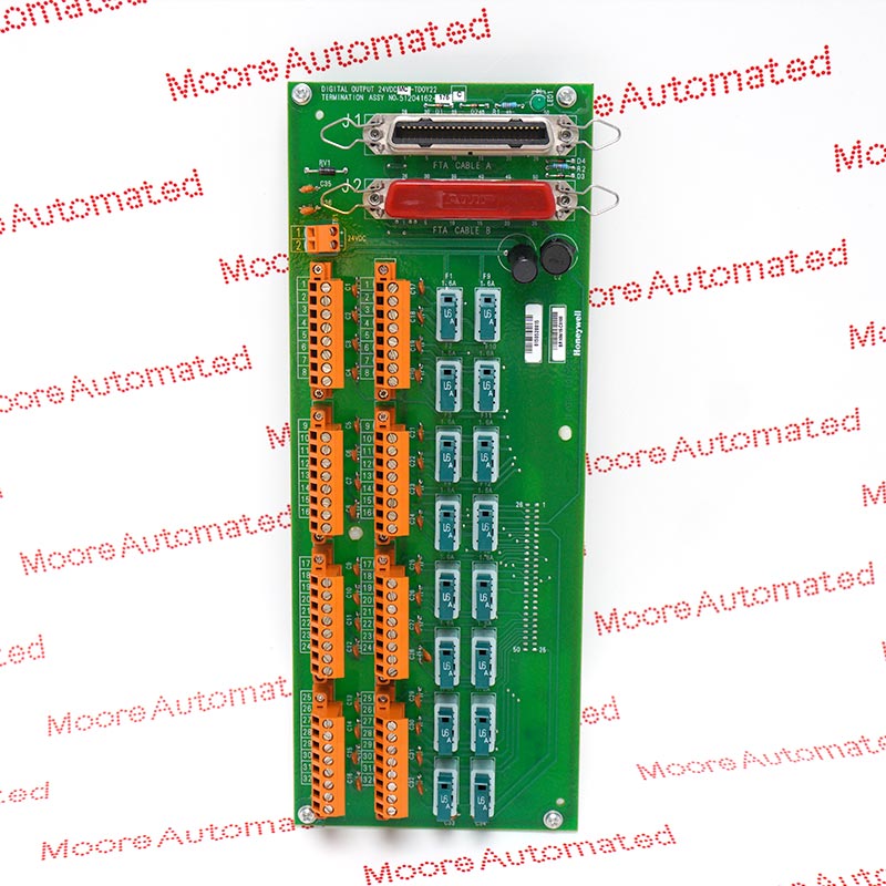
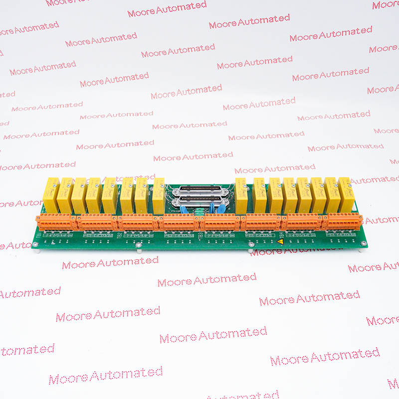
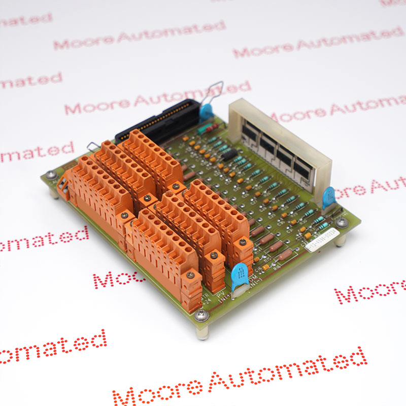
Use the designated TPIX12 or TPIX52 termination arrangement with the correct complete hardware execution and cable. The specification supports self-powered two-wire and system-powered three-wire sensor arrangements, with the stated transmitter-power conditioning limits. Record the existing channel scaling and totalizer configuration before replacement. Verify rate and accumulated counts with a known signal, and account for the separate 20 ms field scan and 500 ms PV update when interpreting the system response. FTA hardware and cables must be stated separately in the supply scope.

Registered Address: 32D Floor Guomao Building, No.388, Hubin South Road, Siming District, Xiamen,Fujian, China
MooreAutomated.com is the official website and primary online platform operated by Moore Automation Limited. The website provides information about the company’s industrial automation parts sourcing services, product coverage and customer support. Moore Automation Limited operates as an independent supplier and is not an authorized distributor or representative of the manufacturers displayed on this website unless expressly stated.