


Registered Address: 32D Floor Guomao Building, No.388, Hubin South Road, Siming District, Xiamen,Fujian, China
ISO 9001:2015 Certified
Our quality management system covers sourcing,testing and dispatch


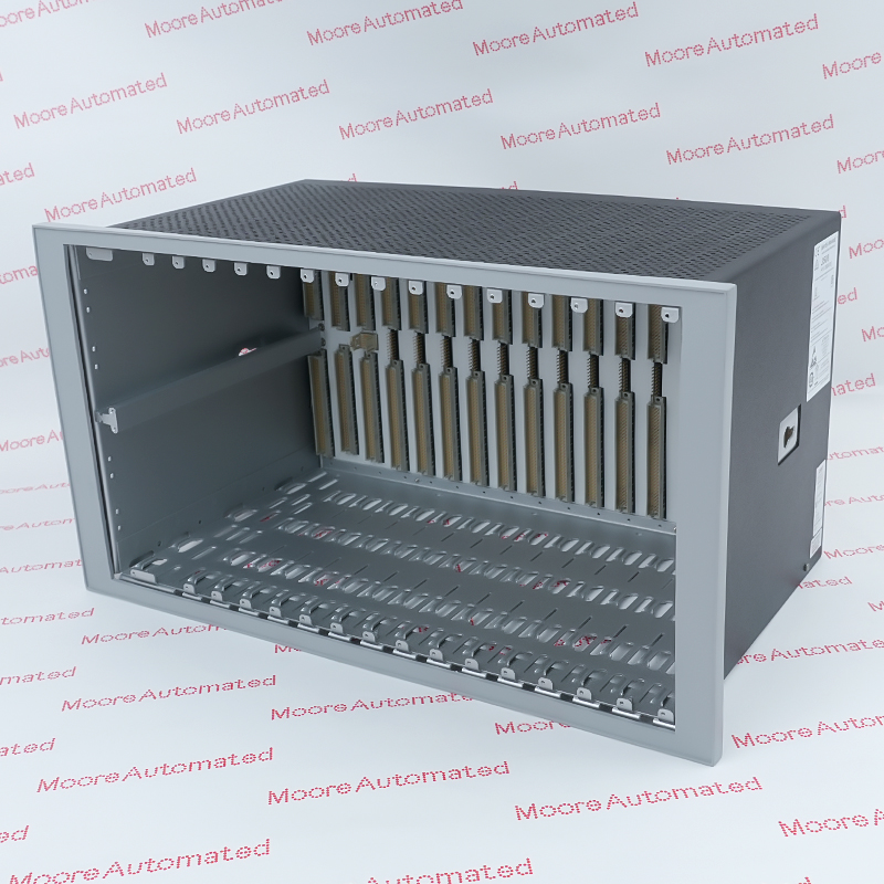
Honeywell's IPC 620-25/35 manual identifies 621-9937 as the Parallel I/O Module (PIOM) in a 621 I/O rack. It connects through a 50-pin parallel link and provides rack-start and slot-address switch settings. Confirm the physical module, rack size, cable, addressing and complete revision before replacement.
Honeywell's February 1988 IPC 620-25/35 User Manual describes the local parallel I/O path from the processor's Parallel Link Driver Module to a PIOM in the 621 I/O rack. It identifies 621-9937 in the switch-setting section. A 50-pin D connector links the processor and PIOM, while a second PIOM port can carry the connection to another rack. The manual specifies a 100-foot maximum data cable length for this local configuration. These statements establish a system arrangement, not independent signal-processing or isolated I/O specifications for the PIOM.
The PIOM switch settings determine rack starting address and slot allocations. The manual says SW1 switches 1 through 8 set the starting address in increments of eight, while other switch banks allocate zero, eight, sixteen or thirty-two addresses to each rack slot. Before service, record the physical module and revision, rack identity, IN/OUT cabling, every switch position, all installed I/O cards and the resulting address map. Follow approved isolation and ESD procedures. After a verified replacement, check rack communication and all affected input and output points. Do not copy generic serial-I/O module specifications onto this parallel interface.
Honeywell describes the PIOM as the rack-side interface for local parallel I/O. The processor's Parallel Link Driver connects to it by a 50-pin D cable, and additional racks can be daisy-chained through the other PIOM port. Check the actual host rack, cable direction, connector condition and module marking; a serial I/O card is a different device.
The manufacturer says 621-9937 SW1 sets each I/O rack's starting address in increments of eight. Other switch banks select how many addresses belong to each slot, from zero through thirty-two. A replacement must preserve the full rack and slot map, not just its own visible switch pattern. Record the installed cards and project configuration before moving hardware.
The 1988 Honeywell manual supports exact 621-9937 PIOM identity and the documented 620-25/35 parallel-I/O topology. Its 100-foot cable and 2048-point figures describe the system arrangement, not the PIOM's weight, isolated-channel count or network bit rate. Current hardware revision, stock condition and compatibility require a physical label and site records in addition to this older PDF.
Confirm 621-9937 on the physical PIOM and match its 621 I/O rack and 620-25/35 processor arrangement. The manufacturer documents a 50-pin parallel cable and starting-address selection by SW1, with per-slot allocations configured separately. Record both connector paths, rack sequence, all switch banks and actual I/O card widths before service. The 2048-point value is a processor-system limit, not a channel rating for this module.
Record original PIOM label, revision, rack position, cable IN/OUT orientation, DIP switch states, slot assignments, terminal wiring and baseline diagnostics. Follow site isolation and ESD practice before exchange. After fitting a verified spare, restore the documented addressing and cables, confirm communication between the processor and every linked rack, and test each affected point. Do not treat a SIOM or a differently numbered PIOM as interchangeable without exact Honeywell compatibility evidence.

Registered Address: 32D Floor Guomao Building, No.388, Hubin South Road, Siming District, Xiamen,Fujian, China
MooreAutomated.com is the official website and primary online platform operated by Moore Automation Limited. The website provides information about the company’s industrial automation parts sourcing services, product coverage and customer support. Moore Automation Limited operates as an independent supplier and is not an authorized distributor or representative of the manufacturers displayed on this website unless expressly stated.