Overview
Manuals
Functional Role
Operating principle
Features:
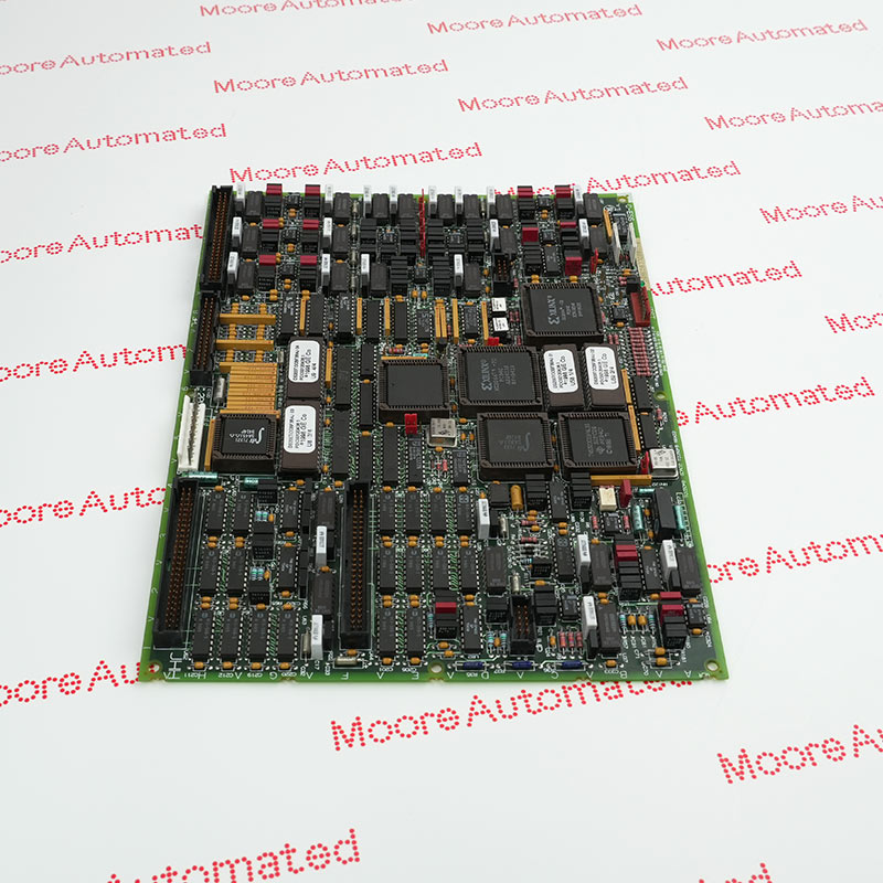
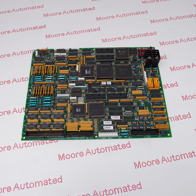
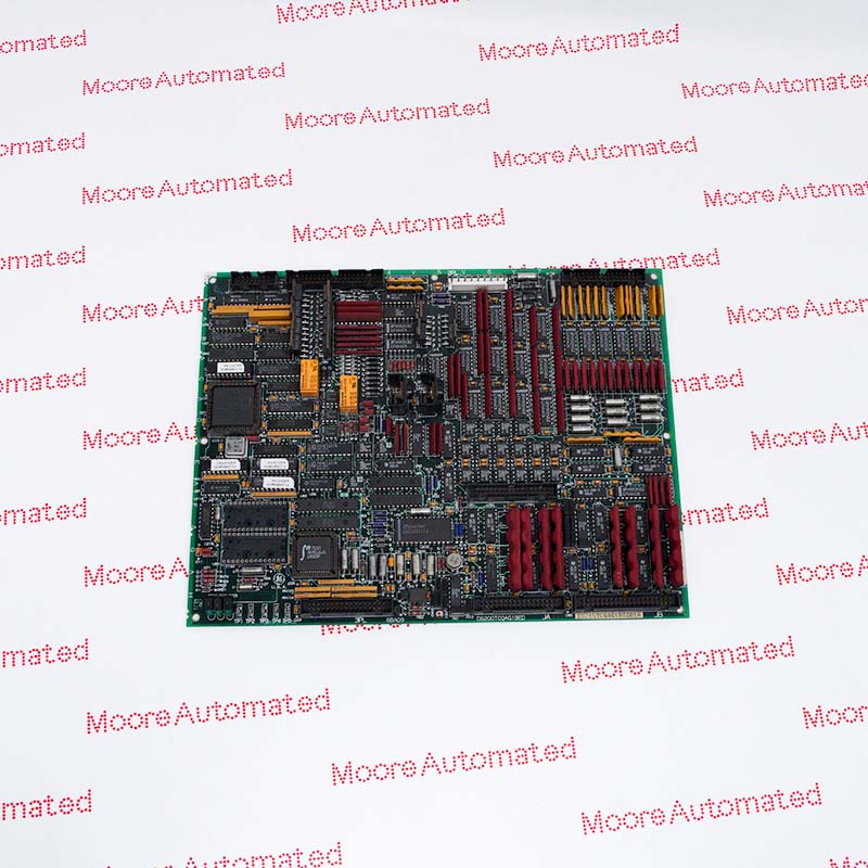
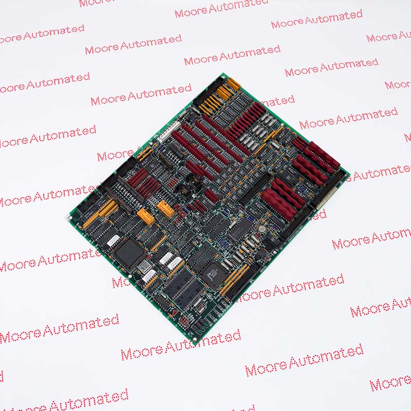
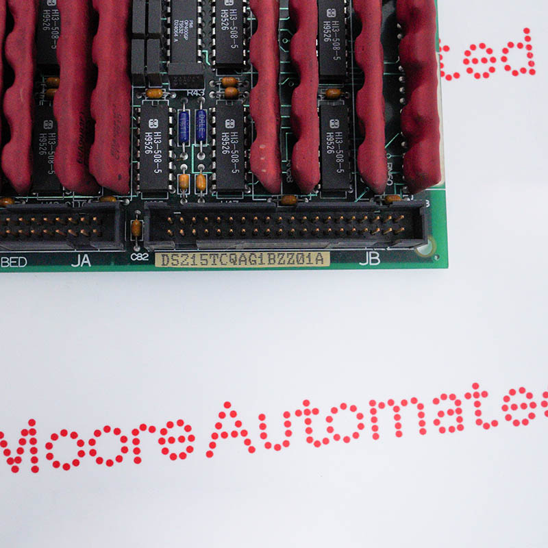
- Circuit Board with Firmware
- GE Boards & Turbine Control Mark V DS200 Series
- Deployed within the main control core, it is used to regulate heavy-duty gas turbines and steam turbines
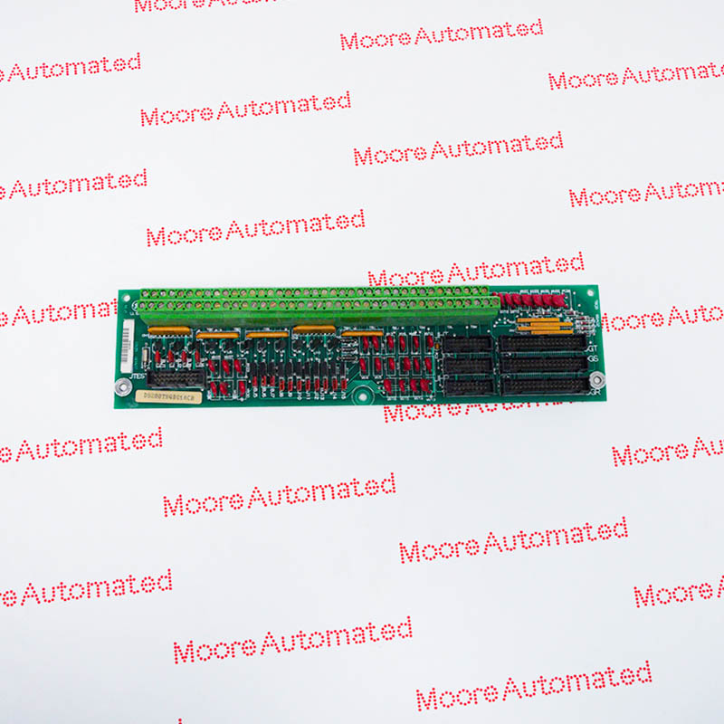
The main function of DS200TCQAG1BFD DS215TCQAG1BZZ01A is to provide high-capacity, high-precision analog signal acquisition and conditioning for gas turbines and steam turbines. This board is a key link connecting the turbine's field physical sensors with the system's main processor, directly affecting the unit's operating efficiency and the accuracy of the main control logic.
The inputs support LVDT (Linear Variable Differential Transformer) position feedback required for precision control valves, thermocouple signals required for critical unit temperature control, vibration signals for monitoring equipment health, pulse counting, and standard 4-20 mA current input. The outputs provide high dynamic response servo valve outputs and 4-20 mA analog control signals for real-time adjustment of the equipment's intake and fuel valves, ensuring absolutely safe and stable operation under high overload and complex industrial environments.
The DS200TCQAG1BFD DS215TCQAG1BZZ01A General Electric Analog I/O Board Circuit Board may still be available for purchase and support from Moore Automated Company beyond End-Of-Life (EOL) by the manufacturer (OEM).
General Electric DS200TCQAG1BFD DS215TCQAG1BZZ01A Analog I/O Board Circuit Board INFO(manual), Link
Important Notice: Other accessories, manuals, cables, calibration data, software, etc. are not included with this equipment unless listed in the above stock item description. All prices are shown in USD.
The TCQA board is the core signal conditioning interface between the turbine hardware and the control system. It scales and filters a large number of critical analog signals, including:
Inputs: Linear Variable Differential Transformer (LVDT), thermocouples, vibration sensors, pulse inputs, and standard 4-20 mA process inputs (e.g., compressor stall detection and fuel flow/pressure).
Outputs: Electro-hydraulic servo valve driver current, relay driver signals, and 4-20 mA monitoring outputs.
The TCQA analog I/O board operates based on a hardware closed-loop signal conditioning and multi-level parallel processing architecture. When a weak analog voltage or current is received from the device via field terminals (e.g., the R1, R2, and R3 core racks), the signal first enters the onboard signal conditioning circuitry for isolation, filtering, and scaling, converting it into a nominal voltage recognizable by the internal analog-to-digital converter (ADC).
The converted digital signal is then written directly to the RAM registers of the upper-level control system or the STCA motherboard via a high-speed bus interface (e.g., a 3PL connector), for use by the system's triple redundant processors (R, S, and T cores) in control algorithm calculations.
Simultaneously, the onboard drive circuitry receives control commands from the microprocessor in real time. Through an internal digital-to-analog converter (DAC) and power amplification, the electrical signal is converted into a precise current output, dynamically driving a servo valve actuator, thus forming a complete high-speed field industrial closed-loop control process.