

Registered Address: 32D Floor Guomao Building, No.388, Hubin South Road, Siming District, Xiamen,Fujian, China
ISO 9001:2015 Certified
Our quality management system covers sourcing,testing and dispatch

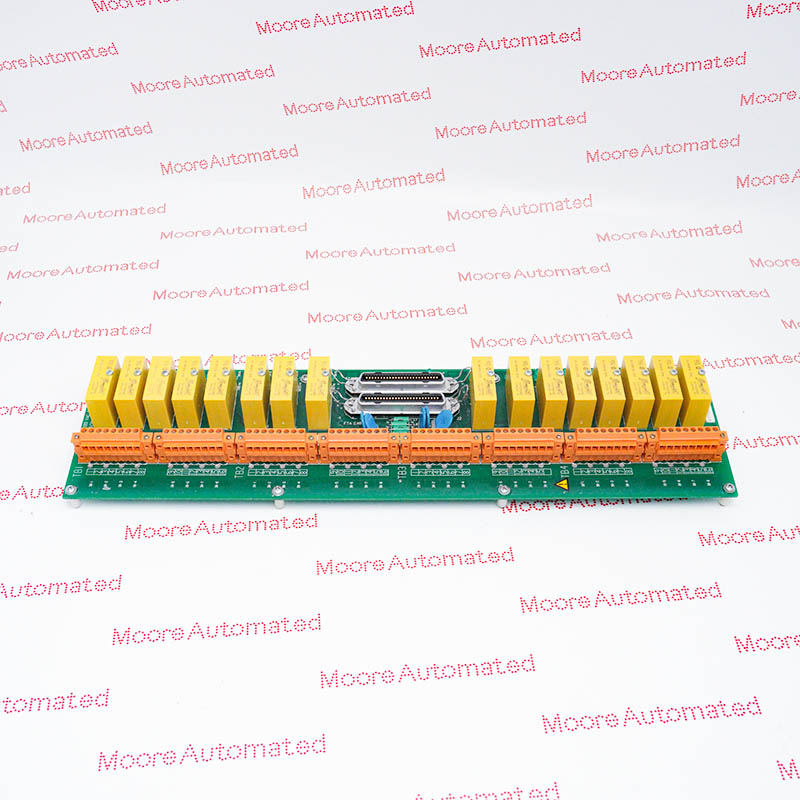
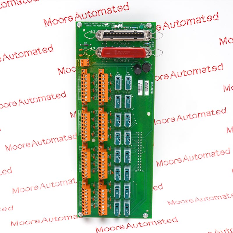
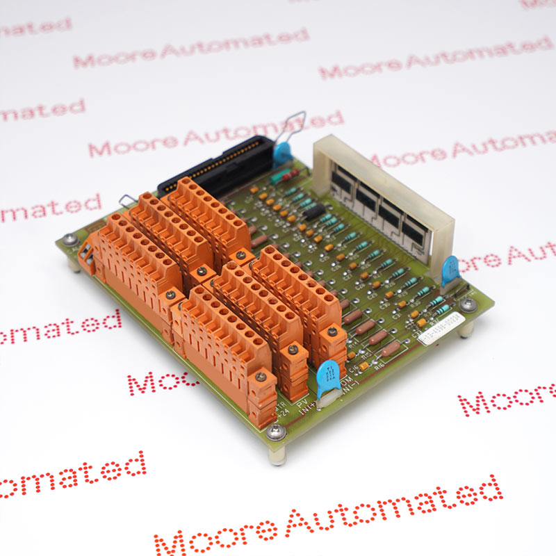
CC-GDIL11 is a Honeywell Series C redundant GI/IS digital input termination assembly, with 51306315-175 shown in the manufacturer board drawing. The nominal 12-inch IOTA handles up to 32 switch or proximity-detector inputs through sixteen MTL4516 isolators. In the documented MTL4517 system line-fault arrangement, usable field capacity becomes 30 inputs because the final channel pair is reserved for fault reporting and termination.
The Honeywell CC-GDIL11 is a GI/IS digital input IOTA intended to terminate discrete field circuits for the Series C control platform. Honeywell's hardware matrix lists a 12-inch redundant arrangement with thirty-two channels when sixteen MTL4516 isolators are installed. The board illustration identifies PWA 51306315-175 and shows two CC-PDIL01 IOM positions. The terminal assembly, isolators and input electronics perform different roles; IOM timing, input-processing features and diagnostic behavior should not be treated as intrinsic specifications of the bare IOTA.
The isolator population determines how the final channels are used. For the documented MTL4517 line-fault reporting configuration, only thirty field inputs are available, channel 31 is configured for the fault alarm and channel 32 is unavailable as a normal input. Honeywell's usage diagram requires an MTL4599 dummy in slot 16 whenever any MTL4517 is fitted in slots 1 through 15. Maintenance planning must therefore preserve both physical wiring and the controller's channel assignments. A replacement selected solely by its maximum thirty-two-channel description could leave the fault-reporting arrangement incorrectly configured or create an unsupported field connection.
With the MTL4517 system line-fault arrangement, channels 1 through 30 remain available for field inputs. Channel 31 is assigned to the line-fault alarm and channel 32 is not available as a normal input. Honeywell requires an MTL4599 in slot 16 if any MTL4517 is installed in the first fifteen positions. Preserve this allocation in both physical wiring and the control configuration.
The model-specific diagram routes pairs of switch or proximity-detector circuits through their assigned galvanic isolators before the signals reach the DI IOM. Use the correct sensor and isolator wiring drawing, including the resistor arrangement required when line-fault detection is enabled for switch inputs. Maintain field-wire identification and shield grounding; the IOM's 24 Vdc designation is not permission to apply that voltage directly to an intrinsically safe sensor circuit.
The board illustration shows two CC-PDIL01 positions, and the spare-parts table assigns separate 0.5 A fuses to the upper and lower IOM feeds. The isolators have a separate 2 A feed fuse. IOM redundancy does not eliminate the need to check the isolator supply and each field circuit. Confirm the installed IOM revisions and supported redundancy configuration before replacing or pairing electronics.
A fully populated MTL4516 arrangement uses sixteen dual-channel positions for thirty-two field inputs. Honeywell's CC-GDIL11 usage diagram changes the last position to an MTL4599 dummy when any MTL4517 is fitted in slots 1 through 15. In the documented system line-fault configuration, channel 31 serves the fault alarm and channel 32 cannot be assigned to a normal field input. Before moving wires or replacing isolators, reconcile the physical terminal list with the control database and preserve the intended alarm mapping.
CC-GDIL11 separates the two IOM feeds from the isolator feed. The manufacturer lists 0.5 A fuses, part 51190582-150, at F1 for the upper IOM and F2 for the lower IOM, plus a 2 A fuse, part 51190582-220, at F3 for the isolators. Use the correct position-specific rating and investigate the circuit fault before replacing a fuse. A healthy redundant IOM pair does not prove that the shared isolator supply or every sensor connection is healthy.

Registered Address: 32D Floor Guomao Building, No.388, Hubin South Road, Siming District, Xiamen,Fujian, China
MooreAutomated.com is the official website and primary online platform operated by Moore Automation Limited. The website provides information about the company’s industrial automation parts sourcing services, product coverage and customer support. Moore Automation Limited operates as an independent supplier and is not an authorized distributor or representative of the manufacturers displayed on this website unless expressly stated.