
Registered Address: 32D Floor Guomao Building, No.388, Hubin South Road, Siming District, Xiamen,Fujian, China
ISO 9001:2015 Certified
Our quality management system covers sourcing,testing and dispatch

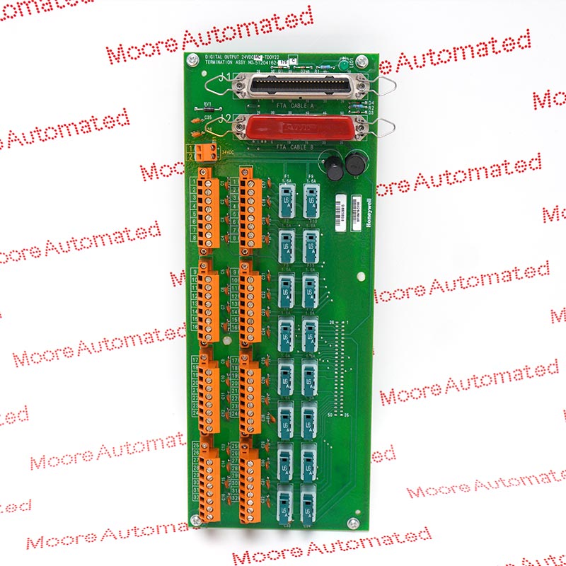
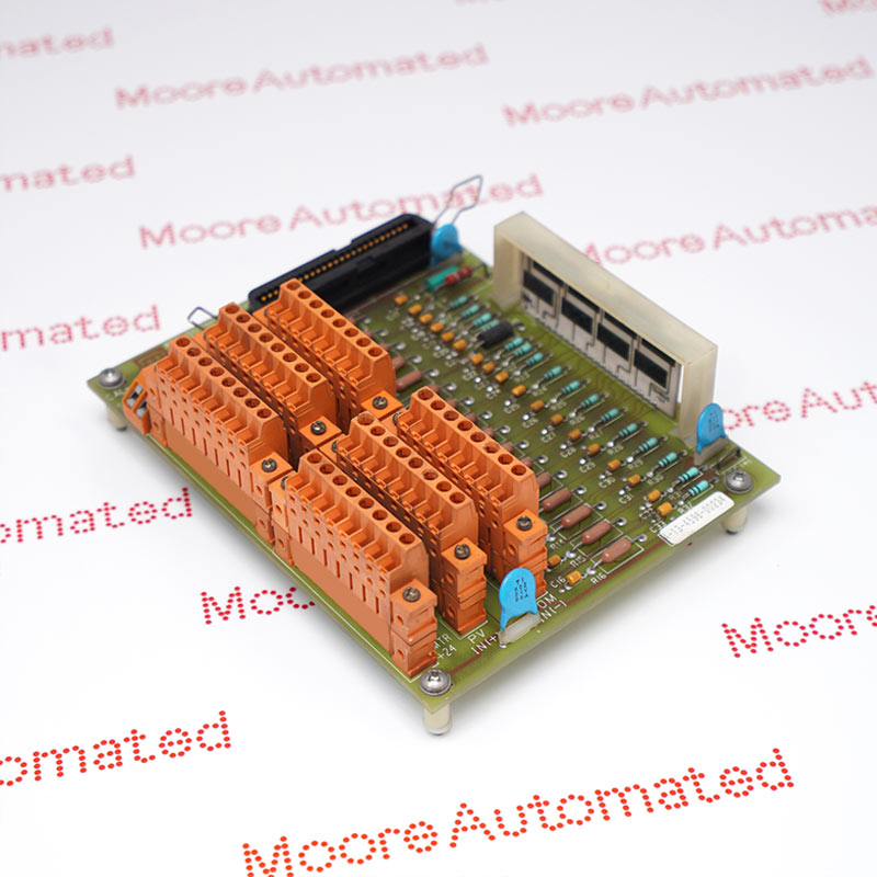
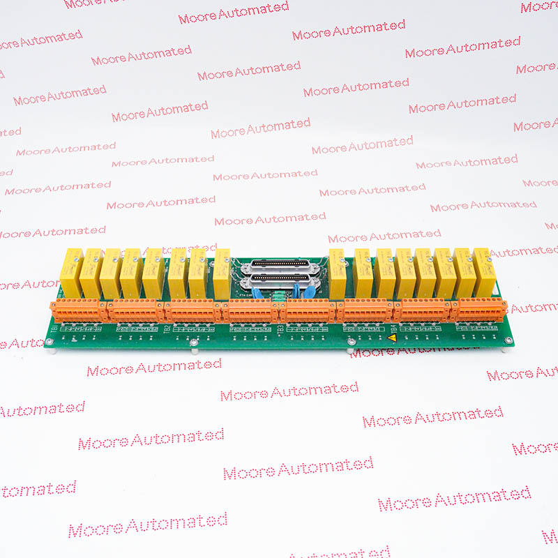
MC-TAIH52 is the coated, screw-terminal field termination assembly for sixteen Honeywell high-level analog input or Smart Transmitter Interface circuits. The size-B layout supports the documented redundant processor arrangement and uses fixed screw terminals for the field wiring.
The Honeywell MC-TAIH52 field termination assembly accepts the wiring for sixteen high-level analog input or Smart Transmitter Interface circuits. Its nonremovable screw terminals distinguish it from the compression-terminal TAIH12 arrangement. Honeywell lists the size-B board for redundant service with the specified processor families. The MC ordering designation identifies the coated execution; the installed processor determines whether the connected instruments are used for conventional analog measurement or the documented smart-transmitter service.
For HLAI operation, the specification lists 0-5 V, 1-5 V and 0.4-2 V ranges, plus 4-20 mA through 250 ohms. The TAIH52 transmitter feed is limited by a 145-ohm resistor and is not individually fused. The common-mode limit and normal low-side common-jumper arrangement must be considered together. Its board footprint is 307.3 by 120.65 mm, excluding cable access and packaging. Preserve wire labels, redundant cable destinations and the complete 51304337-250 assembly identity during replacement.
The sixteen instrument circuits land on nonremovable screw terminals. This changes the field-wiring interface relative to a compression-terminal assembly, even where the processor family and channel count agree. Identify every conductor and restore the approved terminal assignment, shielding and processor cable destinations after replacement.
Honeywell specifies a 145-ohm resistor for transmitter-feed current limiting in this termination arrangement. This is not the enhanced-power current limiter used in another TAIH variant and it is not a fuse rating. Compare instrument supply requirements with the complete installed field circuit.
The HLAI common-mode range is -6 to +5 V peak from DC to 60 Hz. The manufacturer footnote also describes the low-side connection to system common through an FTA jumper. Preserve the engineered reference arrangement rather than changing it solely to obtain a plausible reading.
Identify whether the installed system uses HLAI or Smart Transmitter Interface processing before selecting the replacement. The TAIH52 is a termination assembly for those specified processor pairings, not a universal protocol adapter. Match the fixed screw-terminal layout, coated construction and redundant cable set, then reconcile all sixteen field circuits with the control-system point schedule.
Check instrument current requirements, the resistor-limited supply path and the approved common reference together. The voltage and current ranges describe the documented HLAI processor/FTA combination. Confirm the field polarity and shielding, inspect the fixed terminals and perform the approved measurement checks after installation; a correct board label alone does not prove that field wiring and configured ranges agree.

Registered Address: 32D Floor Guomao Building, No.388, Hubin South Road, Siming District, Xiamen,Fujian, China
MooreAutomated.com is the official website and primary online platform operated by Moore Automation Limited. The website provides information about the company’s industrial automation parts sourcing services, product coverage and customer support. Moore Automation Limited operates as an independent supplier and is not an authorized distributor or representative of the manufacturers displayed on this website unless expressly stated.