
Registered Address: 32D Floor Guomao Building, No.388, Hubin South Road, Siming District, Xiamen,Fujian, China
ISO 9001:2015 Certified
Our quality management system covers sourcing,testing and dispatch

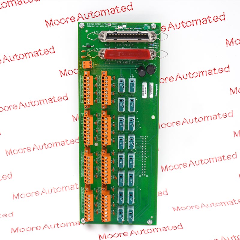
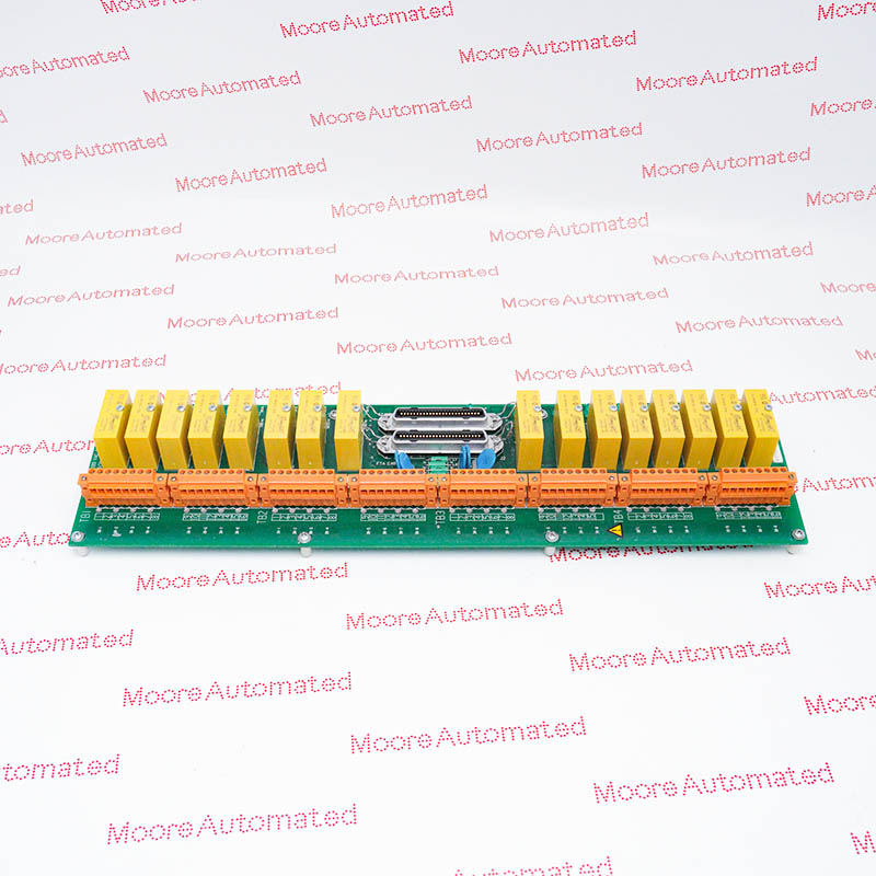
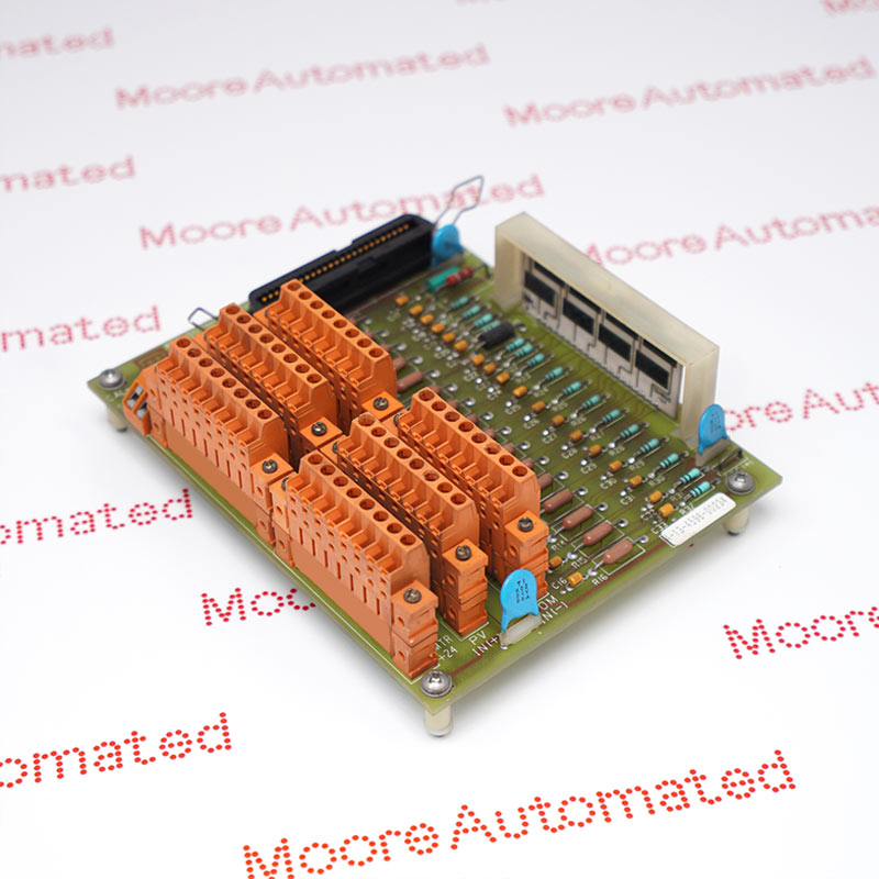
MC-TAOX12 is a Honeywell eight-circuit analog output termination assembly for the redundant PAOX03 arrangement. It uses compression terminals on a size-B board; this record retains the complete 51304335-125 assembly marking.
For the MC-TAOX12 51304335-125 catalog record, Honeywell family documentation establishes the TAOX12 base function as an eight-circuit analog output termination for PAOX03 processors. The MC ordering designation identifies coated construction, while the complete numeric assembly suffix must still be matched to the offered unit. The board uses compression field terminals and the size-B layout for redundancy. It should not be selected as a sixteen-output TAOY termination or as an independent analog signal source.
The PAOX03/TAOX12 specification provides a normal 4-20 mA signal and a directly accessible range of 0.1-21.4 mA. Its 26 mA maximum current is a limit, not a substitute for the normal operating range, and the maximum resistive load is 750 ohms at 22 mA. Output settling is specified at four milliseconds to 98% of the final value. Include receiver and wiring resistance in the loop assessment, and preserve the redundant processor cables and full assembly identification during replacement.
The processor/FTA combination supports a 750-ohm maximum resistive load at 22 mA. Include the field receiver and wiring resistance in the check, and use the configured operating range rather than the 26 mA maximum current figure as the normal control demand. Confirm the receiving device limits separately.
The redundant termination switching hardware is checked once per minute in the documented arrangement. This diagnostic interval is not the analog output update rate. Confirm the installed processor pair and assess the published swap and failover perturbation limits against the process requirements before returning a replaced board to operation.
Trace the two processor-side paths and all eight field output circuits before removal. Preserve cable identification, polarity and the approved shielding arrangement. Similar TAOX designations do not establish that every assembly suffix or connector option is interchangeable, so compare the complete board label and existing terminal positions.
Evaluate the field receiver and cable resistance against the 750-ohm maximum load specified at 22 mA. The normal signal is 4-20 mA, even though an extended 0.1-21.4 mA range and a 26 mA maximum are also documented. Check configured limits and the receiving device specification so an extended or fault-condition value is not mistaken for a normal process command.
The 51304335-125 assembly marking is retained for exact-item matching; the base-family document does not establish interchangeability with every other TAOX12 suffix. Inspect the full supplied label, connector positions and installed redundant cable set. After service, verify the affected field loops and the actual processor transfer arrangement, including the process response to the documented swap and failover perturbations.

Registered Address: 32D Floor Guomao Building, No.388, Hubin South Road, Siming District, Xiamen,Fujian, China
MooreAutomated.com is the official website and primary online platform operated by Moore Automation Limited. The website provides information about the company’s industrial automation parts sourcing services, product coverage and customer support. Moore Automation Limited operates as an independent supplier and is not an authorized distributor or representative of the manufacturers displayed on this website unless expressly stated.