
Registered Address: 32D Floor Guomao Building, No.388, Hubin South Road, Siming District, Xiamen,Fujian, China
ISO 9001:2015 Certified
Our quality management system covers sourcing,testing and dispatch

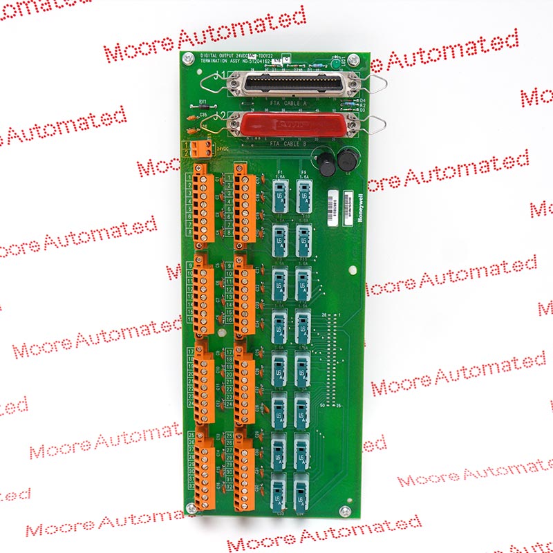
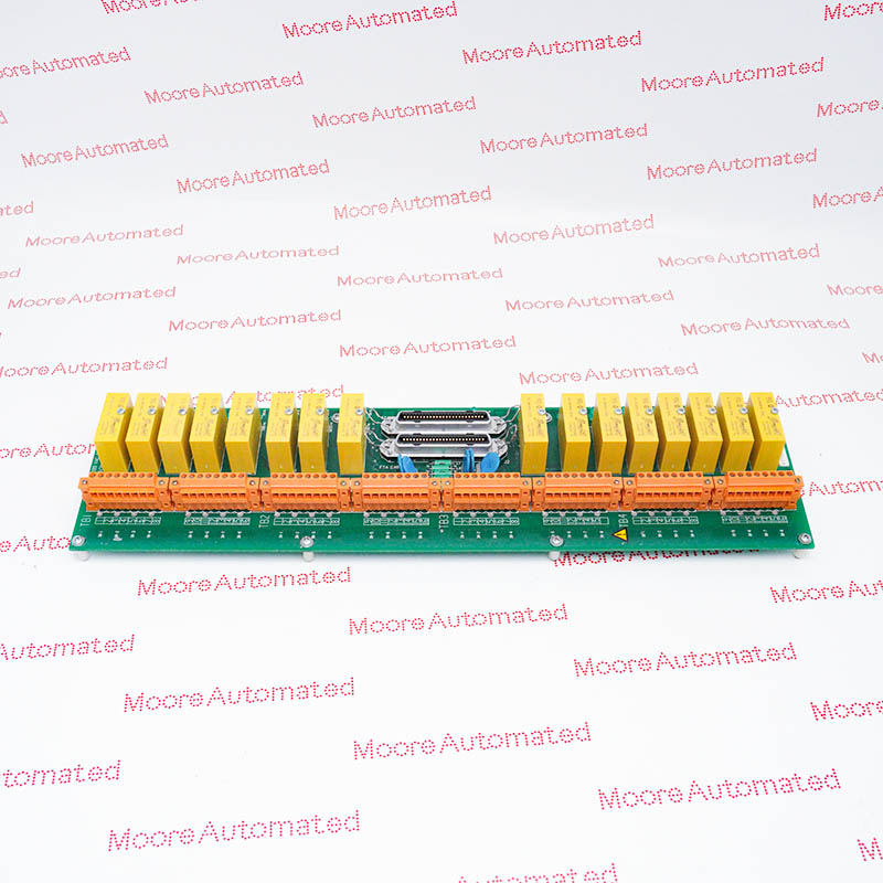
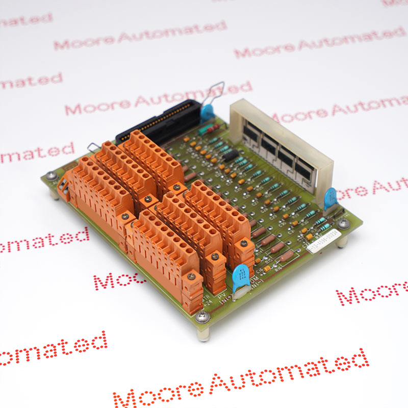
MC-TDOR12 is a coated sixteen-output relay field termination assembly with compression terminals. It is specified for the PDOX02 architecture, with jumper-selectable normally open or normally closed contacts and a 5 A rating at 120 V AC for resistive loads.
Honeywell MC-TDOR12 is a coated relay field termination assembly for sixteen PDOX02 output commands. The field connections use compression terminals, and each output has an individually selected normally open or normally closed contact form. Silver-alloy electromechanical contacts provide the documented channel isolation. This board is intended for the stated power-contact service, not low-level signal switching or high-frequency pulse generation, and it must be matched to the actual field load.
The specification allows 5 A at 120 V AC for a resistive load, but only 0.5 A at 125 V DC; a separate 2 A rating applies at 30 V DC. The minimum load current is 100 mA. Each contact has a 22-ohm/0.1-microfarad suppression network and a 6 A, 125 V slow-blow fuse. With a 15 ms maximum operate or release time and a 360-cycle-per-hour rated-load limit, the relay behavior must be considered in the process command sequence.
The load-current rating changes with voltage and AC or DC service. Five amperes is the 120 V AC resistive rating, while the specified 125 V DC limit is 0.5 A. Apply the manufacturer load derating and minimum current requirement to every connected circuit.
Operate and release times are each 10 ms typical and 15 ms maximum. The rated-load repetition limit is 360 cycles per hour. These power relays are not a substitute for a high-speed pulse output; check the required command sequence and expected contact wear.
The field conductors terminate through compression connections on a size-B board. Preserve the terminal mapping and NO/NC jumper positions when moving from the installed assembly. Inspect the contact fuses and processor cable as part of the replacement, not only the external wire labels.
Compare each connected load with the separate 120 V AC, 30 V DC and 125 V DC current ratings. Include the minimum 100 mA contact-current requirement and manufacturer derating for nonresistive loads. Review the 360-cycle-per-hour rated-load limit against the actual command duty; contact life depends on the load and switching conditions.
Document the compression-terminal assignments, individual contact fuses and all output contact-selection jumpers before removing the board. Check the coated construction and full MC-TDOR12 assembly label. Restore the approved wiring and processor cable, then verify relay action and the receiving equipment response under the site procedure without altering the established protective circuit.

Registered Address: 32D Floor Guomao Building, No.388, Hubin South Road, Siming District, Xiamen,Fujian, China
MooreAutomated.com is the official website and primary online platform operated by Moore Automation Limited. The website provides information about the company’s industrial automation parts sourcing services, product coverage and customer support. Moore Automation Limited operates as an independent supplier and is not an authorized distributor or representative of the manufacturers displayed on this website unless expressly stated.