
Registered Address: 32D Floor Guomao Building, No.388, Hubin South Road, Siming District, Xiamen,Fujian, China
ISO 9001:2015 Certified
Our quality management system covers sourcing,testing and dispatch

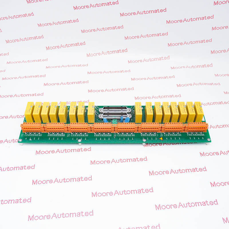
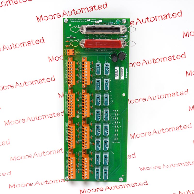
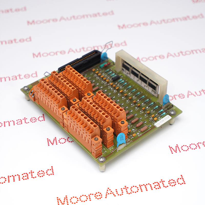
MC-TDOY62 is a coated 32-circuit digital output termination assembly for the Honeywell PDOY22 architecture. It uses fixed screw terminals and open-collector sinking outputs, with group-current limits that differ from the compression-terminal TDOY22 version.
Honeywell MC-TDOY62 provides the screw-terminal field interface for thirty-two PDOY22 digital outputs. The documented circuit is an open-collector NPN sinking output with a 15-30 V DC field-voltage range. This is not an electromechanical relay termination. Each output is rated for up to 0.5 A, but the eight-point group and complete-board limits also apply. The MC ordering prefix identifies the conformally coated version of this termination arrangement.
The TDOY62 grouping is important when several outputs operate together: Honeywell allows 1.2 A for each eight-point group and 5 A over all thirty-two circuits. A single fuse serves each group of eight, unlike the two-point grouping on TDOY22. The specification gives a maximum 0.5 V ON-state drop at 0.5 A and 0.5 microampere maximum OFF leakage. Match these characteristics to the field loads, preserve the existing power grouping and allow for the 307.3 by 120.65 mm board footprint.
Each group of eight outputs shares a 1.2 A limit and one fuse. Adding eight individual 0.5 A ratings would exceed the permitted group load. Review simultaneous operating states and load inrush against the complete specification rather than sizing the circuit from channel ratings alone.
The output transistor provides an NPN open-collector sinking path. The field supply and load wiring must match that arrangement; it is not a potential-free relay contact or sourcing output. Verify polarity, supply return and required suppression using the approved field circuit.
Honeywell specifies a 1.6 A, 125 V fuse measuring 5.5 by 17.2 mm for the documented grouping. The fuse rating is not the continuous group-current allowance. Retain the approved protective arrangement and investigate a failed group before fitting replacement hardware or restoring the field supply.
Check the 0.5 A point, 1.2 A eight-point group and 5 A board limits together using the actual simultaneous load schedule. The ON-state drop and OFF leakage also affect compatibility with the receiving device. Identify any load inrush and external suppression requirements from the approved design; a nominal 24 V rating alone does not establish suitability.
Identify the eight-point fuse groups and retain field-supply segregation when disconnecting the fixed screw terminals. Record every output assignment and the processor cable routing. Compare the coated MC construction and exact board marking before installation, then test permitted output states and actual load operation under the site procedure without bypassing the shared protective devices.

Registered Address: 32D Floor Guomao Building, No.388, Hubin South Road, Siming District, Xiamen,Fujian, China
MooreAutomated.com is the official website and primary online platform operated by Moore Automation Limited. The website provides information about the company’s industrial automation parts sourcing services, product coverage and customer support. Moore Automation Limited operates as an independent supplier and is not an authorized distributor or representative of the manufacturers displayed on this website unless expressly stated.