
Registered Address: 32D Floor Guomao Building, No.388, Hubin South Road, Siming District, Xiamen,Fujian, China
ISO 9001:2015 Certified
Our quality management system covers sourcing,testing and dispatch

Honeywell MU-TPIX12 51304084-100 parameters below are taken from a multi-page technical document that identifies the model. Verify the supplied hardware revision before installation.
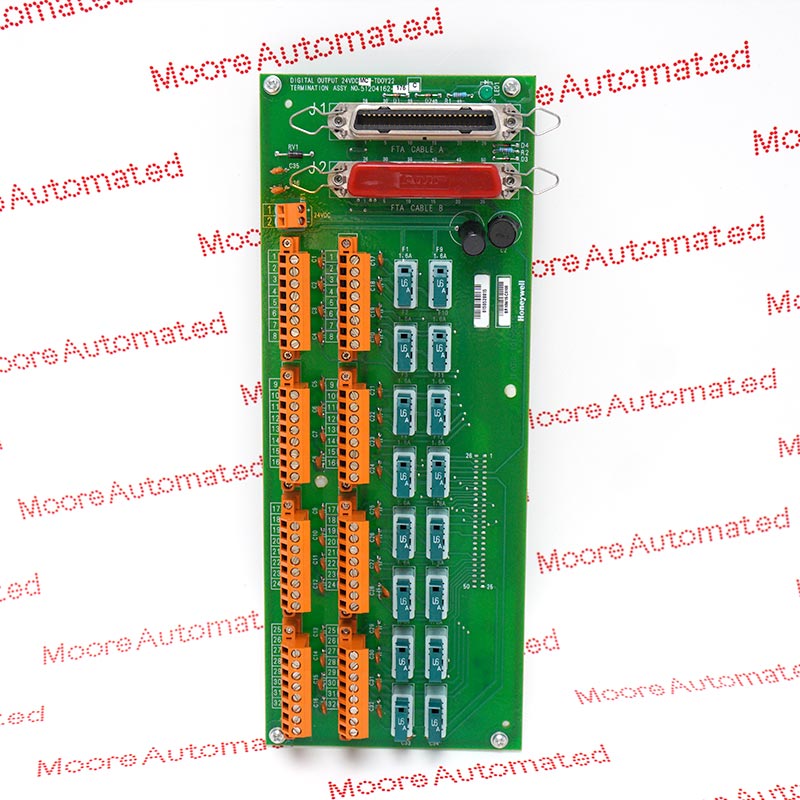
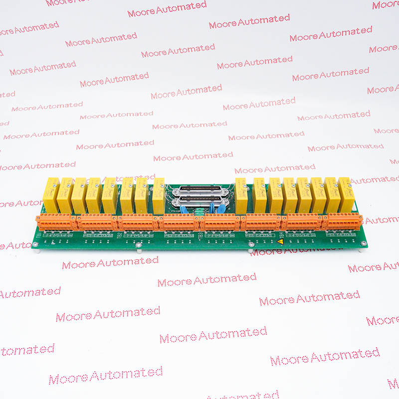
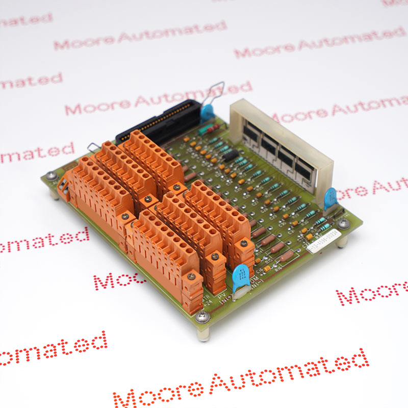
Honeywell MU-TPIX12 is the field termination assembly for eight PPIX02 pulse-input circuits. The published processor/FTA table includes self-powered two-wire sensors, system-powered three-wire sensors, pulse-voltage signals and contact inputs. Rectangular and sine-wave signals are specified, but the manufacturer prohibits mixing sine waves with square waves or contacts on the same FTA. Compression terminals provide the field connections on the uncoated size-B board; the associated processor performs rate measurement and totalization.
The headline frequency range is 1 Hz to 20 kHz under the stated conditions. With mixed signal amplitudes, the allowed maximum falls with FTA cable length, reaching 9 kHz for a 50 m cable. Filter-jumper settings also change the minimum pulse dwell and usable frequency. The specification gives a 20 ms field scan and 500 ms process-value update for eight channels. These are system processing figures, not independent timing guarantees from a passive terminal connection.
Rectangular and sinusoidal inputs are documented, but sine waves must not be mixed with square-wave or contact signals on the same FTA. Identify all eight connected sensor types before assigning channels. Mechanical terminal compatibility does not establish that the complete waveform combination meets the processor specification.
For mixed signal amplitudes, the manufacturer reduces the maximum frequency to 9 kHz with 50 m FTA cables, 13 kHz at 30 m, 15 kHz at 20 m and 18 kHz at 10 m. The 20 kHz figure applies at 5 m under the stated conditions.
For the documented three-wire connection, transmitter power is 23-25 V DC at open circuit and 21 V at 115 mA load, with a 150 mA maximum short-circuit current. Compare the sensor requirement and field wiring with that specific arrangement before applying system power.
At 20 kHz the published minimum high and low dwell is 25 microseconds with the processor filter jumper in its storage position. The H setting corresponds to 50 microseconds at 10 kHz, and L to 500 microseconds at 1 kHz. Verify the installed waveform, cable length and filter together rather than treating each maximum as simultaneously available.
Record the sensor wiring type, channel assignments and processor cable before replacing the FTA. Preserve the required waveform grouping and check the instrument supply where system-powered sensors are used. After reconnection, compare measured frequency and accumulated counts with an approved reference under the site test procedure; the processor database and scaling must remain consistent with the actual pulse source.

Registered Address: 32D Floor Guomao Building, No.388, Hubin South Road, Siming District, Xiamen,Fujian, China
MooreAutomated.com is the official website and primary online platform operated by Moore Automation Limited. The website provides information about the company’s industrial automation parts sourcing services, product coverage and customer support. Moore Automation Limited operates as an independent supplier and is not an authorized distributor or representative of the manufacturers displayed on this website unless expressly stated.