Overview
Manuals
Main Features
Working principle
Features:
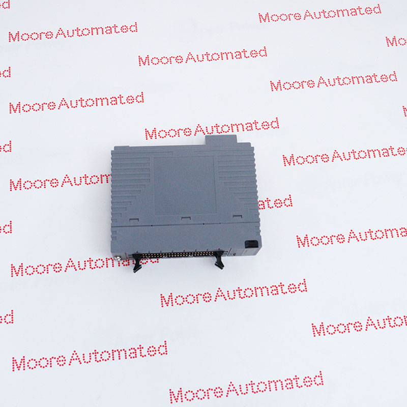
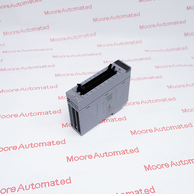
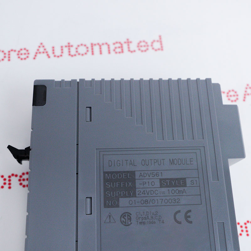
- Digital Output Module (64-channel, 24 V DC, Isolated)
- The Digital Output Modules output 32-channel or 64-channel transistor contact signals
- The ADV551 and ADV561 can be used in dual redundant configuration
The Yokogawa ADV561-P10 S1 is a high-density 64-channel digital output module designed for CENTUM VP distributed control systems. It serves as the main interface, transmitting ON/OFF command signals from the controller to numerous field devices, such as indicator lights, miniature solenoid valves, and auxiliary relays.
Its high channel density makes it ideal for large industrial plants with limited cabinet space, enabling centralized control of large signal networks or low-power actuator networks.
The ADV561-P10 S1 YOKOGAWA Digital Output Module may still be available for purchase and support from Moore Automated Company beyond End-Of-Life (EOL) by the manufacturer (OEM).
YOKOGAWA ADV561-P10 S1 Digital Output Modules DATASHEET(manual), Link
Important Notice: Other accessories, manuals, cables, calibration data, software, etc. are not included with this equipment unless listed in the above stock item description. All prices are shown in USD.
Designed for reliability in mission-critical environments, this module supports dual redundancy to prevent system downtime. All 64 channels are designed to handle 24V DC signals and include built-in overcurrent and overtemperature protection. The "S1" suffix indicates a special version, typically offering greater durability or specific terminal compatibility to ensure stable operation in industries such as oil refining, power generation, and chemicals.
The ADV561-P10 S1 receives digital logic commands from the field control unit (FCU) via the system bus. These low-level electronic signals are processed and isolated by internal optocouplers to shield against electrical noise from the field side. After isolation, the signal triggers a solid-state switching transistor (sink type), which connects to a 24V DC external power supply circuit to power the connected field load.