Get Repair Quote
Name
Company *
Phone *
Email *
Address
City
State / Province / Region
Zipcode
Country
Quantity *
Part Number *
Manufacturer
Preferred Condition
Additional Information
Cancel
Yokogawa ADV561-P11 S1
· Product image is representative; revision or series may vary. Contact us to request a specific version.

ADV561-P11 S1

Digital Output Modules
In Stock

Product Information:

Digital Output Modules

The Digital Output Modules output

32-channel or 64-channel transistor

contact signals.

The ADV551 and ADV561 can be used

in dual redundant configuration.

Expand All
Collapse all

Technical specifications for ADV561-P11 S1

  • Manufacturer:
    Yokogawa
  • Product Category:
    DCS System
  • Estimated shipping dimensions:
    12.5 x 20 x 14.8 cm
  • Weight:
    0.25 kg
  • Tariff Code:
    8537101190
  • Country of origin:
    Japan
  • Place of shipment:
    Xiamen, Fujian, China
  • Number of output channels:
    64 channels
  • Rated applied voltage:
    24 V DC
  • Load voltage:
    24 V DC, 100 mA
  • External power supply voltage range:
    20.4 to 26.4 V DC
  • Output ON voltage maximum value:
    2 V DC
  • Leak current maximum value when output OFF:
    0.1 mA
  • Output format:
    Current sink
  • Output response time:
    3 ms or less (for status output) 10 ms or less (for mixed status and pulse outputs)
  • Maximum current consumption:
    700 mA (5 V DC) 120 mA (external power supply)
  • Stock:
    10

Information

Overview Manuals Key Applications Installation & Compatibility

Features:

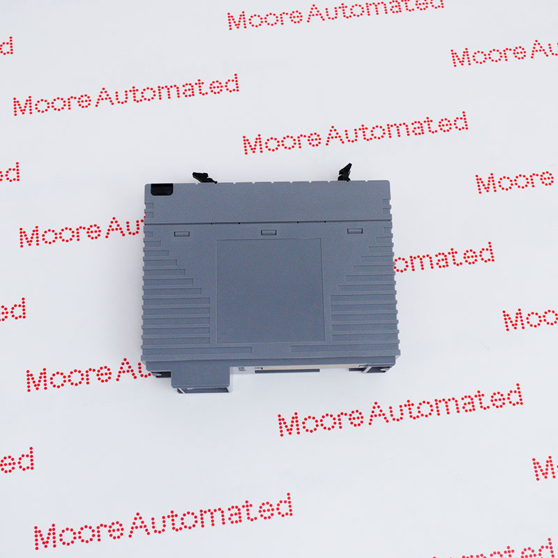
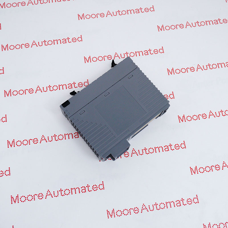
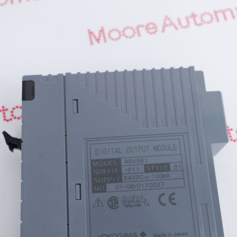
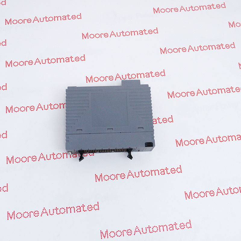
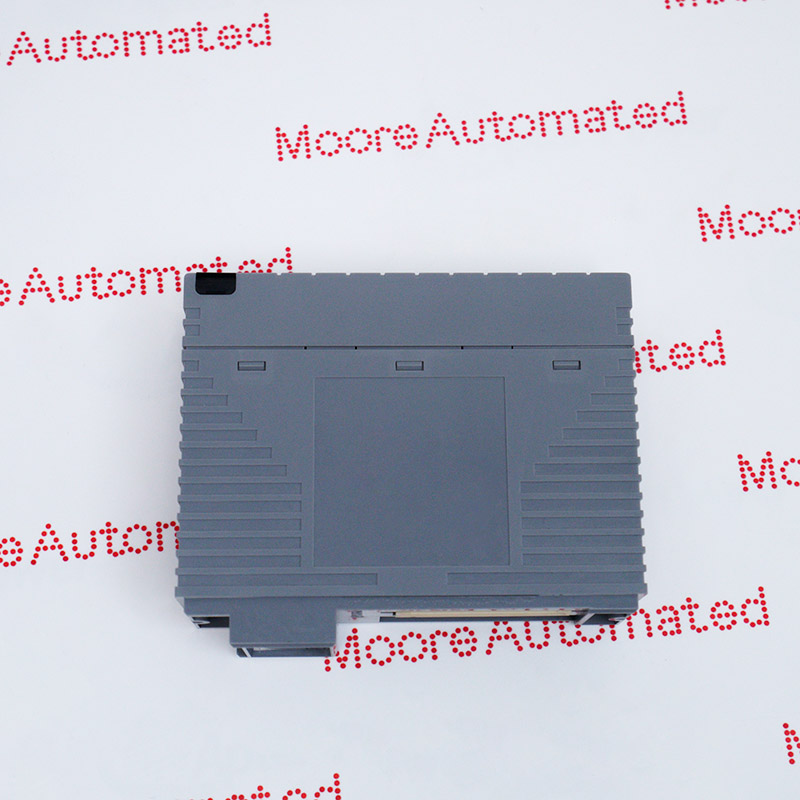
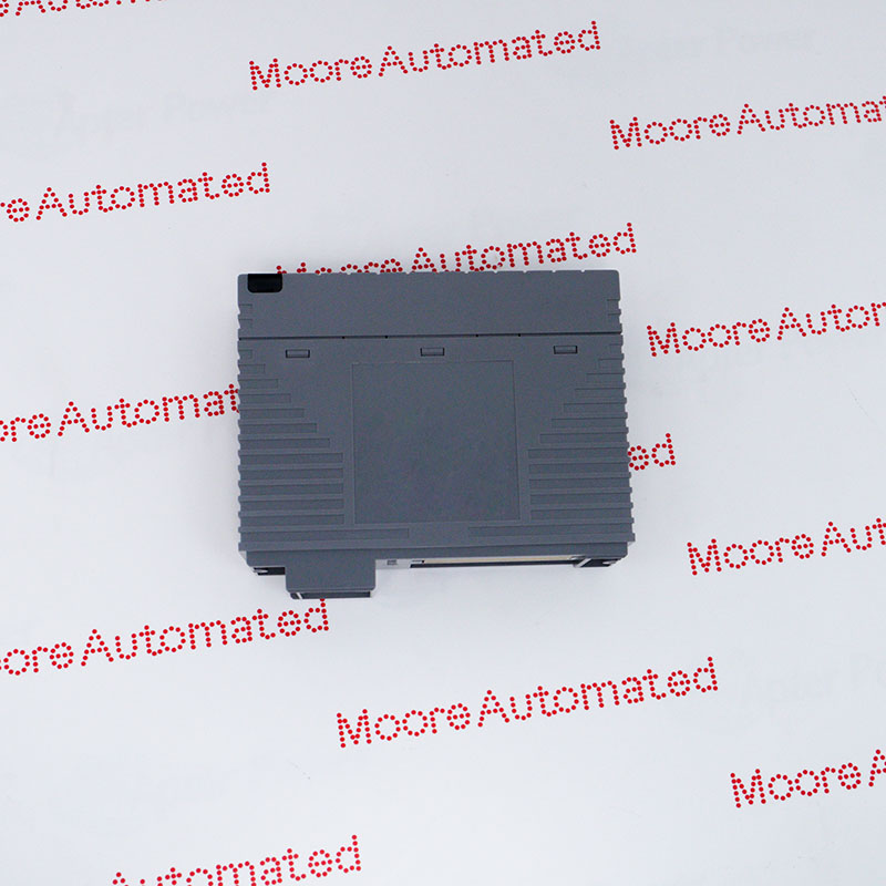
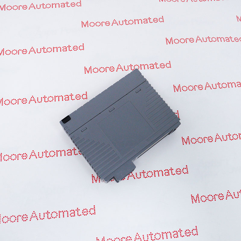
  • Digital Output Module (64-channel, 24 V DC, Isolated)
  • The Digital Output Modules output 32-channel or 64-channel transistor contact signals
  • The ADV551 and ADV561 can be used in dual redundant configuration
The Yokogawa ADV561-P11 S1 is a 64-channel, 24V DC digital output module designed for CENTUM VP FIO systems. Compliant with ISA G3 standards, this module offers excellent corrosion resistance in harsh industrial environments.

It supports high-density output and dual redundancy configurations, providing isolated output signals for field devices such as relays and solenoid valves. Internally, the module employs optocoupler isolation and current-sinking transistors to translate control logic into field commands and features self-diagnostic capabilities.

The ADV561-P11 S1 YOKOGAWA Digital Output Module may still be available for purchase and support from Moore Automated Company beyond End-Of-Life (EOL) by the manufacturer (OEM).
YOKOGAWA ADV561-P11 S1 Digital Output Modules DATASHEET(manual), Link Important Notice: Other accessories, manuals, cables, calibration data, software, etc. are not included with this equipment unless listed in the above stock item description. All prices are shown in USD.
  1. Industrial Automation: Serves as a critical interface for controlling high-density output devices such as solenoid valves, relays, and status indicators in power plants, refineries, natural gas plants, and manufacturing plants.
  2. Safety Systems: Used in ProSafe-RS safety instrumented systems to provide reliable, highly available control for critical safety loops.
  3. Redundancy Configuration: Supports dual redundancy settings to ensure system uptime; if one module fails, the backup module maintains control without interrupting the process.
This module requires specific accessories for full integration:
 
  • Cables: Typically AKB337 signal cables are used.
  • Jack Boards: Typically used with relay boards (such as ARM55D or ARM55W) to facilitate external field wiring.
  • System Integration: Configuration and calibration are performed using Yokogawa's software tools (such as the CENTUM VP engineering environment).

Ask our team:

  • How does the ADV561-P11 S1 ensure deterministic operational stability under multivariable electrical, thermal, and environmental stress conditions?
    The ADV561-P11 S1 typically follows stability-centric design principles, aiming to maintain consistent operational behavior under power supply voltage fluctuations, temperature gradients, and external electromagnetic disturbances.
  • How does the ADV561-P11 S1 achieve interface abstraction and cross-domain compatibility across heterogeneous system topologies?
    The ADV561-P11 S1 is typically positioned as an interface module that facilitates electrical and logical compatibility between different system architectures and supports structured integration into a multi-component ecosystem.
  • What signal integrity protection mechanisms does the ADV561-P11 S1 architecture employ under high-frequency or noise-dense operating conditions?
    The ADV561-P11 S1 typically utilizes design strategies aimed at minimizing signal degradation phenomena such as signal attenuation, jitter accumulation, and phase distortion. These strategies are achieved through impedance control and noise suppression principles.
  • How does the ADV561-P11 S1 structurally address lifecycle reliability and parameter drift suppression under long-term operating conditions?
    The ADV561-P11 S1 is typically evaluated within a reliability engineering framework that considers long-term stability, thermal cycling durability, and gradual parameter drift under continuous use conditions.
  • What are the inherent electromagnetic compatibility (EMC) design principles of the ADV561-P11 S1 when deployed in high-density electronic environments?
    The ADV561-P11 S1 typically follows EMC design methodologies aimed at reducing susceptibility to electromagnetic interference while maintaining controlled emission characteristics.
Quantity
Upload
(gif, jpg, jpeg, png, bmp, doc, docx, xls, xlsx, ppt, pdf, csv)
For more information on how your data is processed and stored by Moore automated please read our privacy policy.
Trusted by 5,000+ plants worldwide | Backed by our vast inventory of top-tier control parts, drives and servo motors, fast shipments are dispatched to cover your urgent needs. ABOUT US >>
Moore Disclaimer: Moore Automated's sales automation equipment and related solutions are intended for industrial automation and business operational efficiency improvement purposes only. Product information, technical parameters, and application cases are for reference only and do not constitute an absolute guarantee of performance for any specific industry, scenario, or final application. Actual equipment performance may vary depending on factors such as the usage environment, system integration method, and maintenance conditions. Users should confirm compatibility and safety based on professional technical assessments. Moore Automated assumes no liability for any direct or indirect losses caused by improper use, modification, or failure to operate according to specifications, to the extent permitted by law.