Overview
Manuals
Operating principle
Component Profile & Enclosure Rules
Features:
- The core function group identifier indicates the IGBT driver/source bridge interface board
- Original basic hardware assembly configuration and voltage level
- GE EX2100 / EX2100e Excitation Control Systems and heavy-duty Innovation Series drive assemblies
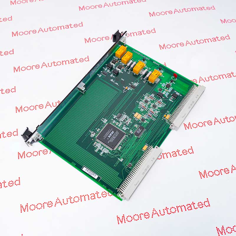
This circuit board is widely used in GE's innovative series drive control systems, EX2100 excitation systems, and Mark VI turbine control systems. Its core function is to serve as a precise electrical data interface between the low-voltage digital control core (e.g., the drive control motherboard) and the underlying high-voltage power module (IGBT power bridge).
It can simultaneously manage two sets of programmable logic devices (EPLDs), responsible for the lossless transmission of high-frequency switching signals from the upper layer to the power inverter side, thereby achieving precise current switching control of the excitation current of large-capacity motors, generator sets, or high-power inverter actuators.
The IS200BICLH1AED GENERAL ELECTRIC Bridge Interface Card may still be available for purchase and support from Moore Automated Company beyond End-Of-Life (EOL) by the manufacturer (OEM).
GENERAL ELECTRIC IS200BICLH1AED Bridge Interface Card INFO(manual), Link
Important Notice: Other accessories, manuals, cables, calibration data, software, etc. are not included with this equipment unless listed in the above stock item description. All prices are shown in USD.
Based on high-speed digital level conversion and a hardware closed-loop thermoelectric protection mechanism, during the operation of the drive or excitation system, the high-frequency PWM trigger command issued by the main control board is sent to the interface card via a 20MHz synchronous clock signal.
The onboard level conversion and logic conditioning circuits respond quickly, converting weak current logic commands into specific amplitude voltages and currents sufficient to safely and efficiently drive the gates of high-power IGBTs, thereby controlling the rapid switching of the power bridge.
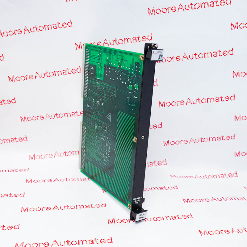
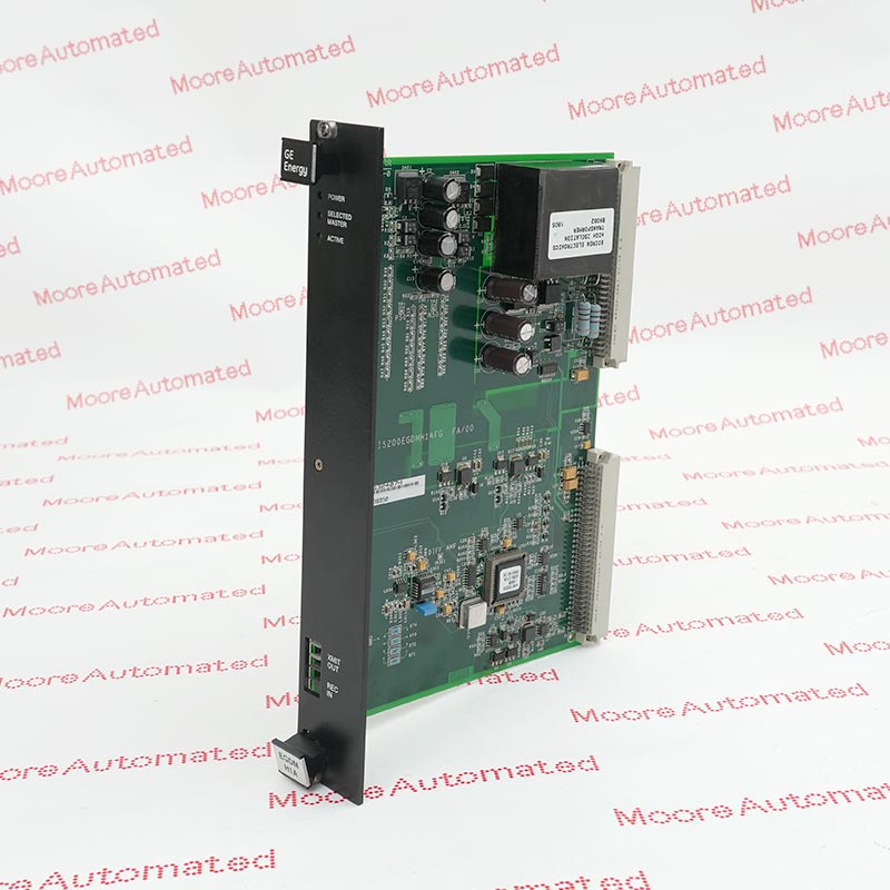
1.Hardware Slot Requirements: According to the EX2100 standard panel documentation, this VME rack module must be installed in slot 5 to ensure proper backplane routing and power distribution.
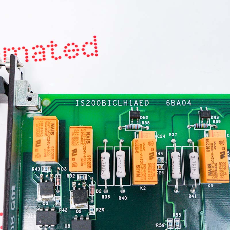
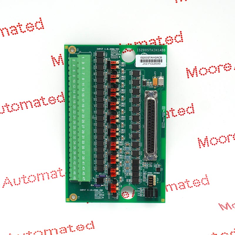
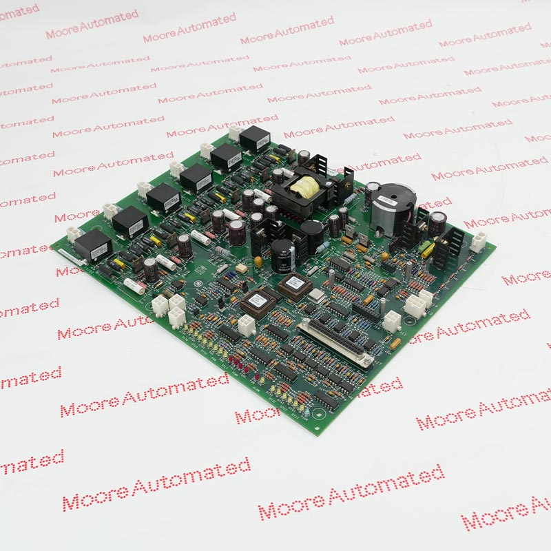
2.Board Composition: This board layout includes approximately 73 high-stability metal film resistors, 31 noise-filtering capacitors, 15 integrated circuits, and 4 physical electromechanical relays.
3.Conformal Coating Protection: To cope with the abrasive conductive dust particles, high humidity, and high temperature environment commonly found in turbine nacelles, the H1AED layer employs a micro-conformal coating covering the entire board surface.