Overview
manual
Protection Functions
Communication & Setup
Features:
- Combined voltage and frequency protection
- Four phase-voltage protection elements
- Two ground overvoltage and two frequency elements
- Modbus RTU communication through RS232 and RS485
- Twenty-four event records and 24-cycle oscillography
- Configurable logic, digital inputs, outputs, and breaker control
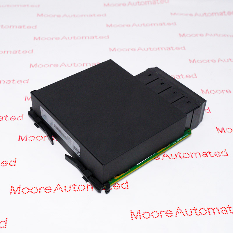
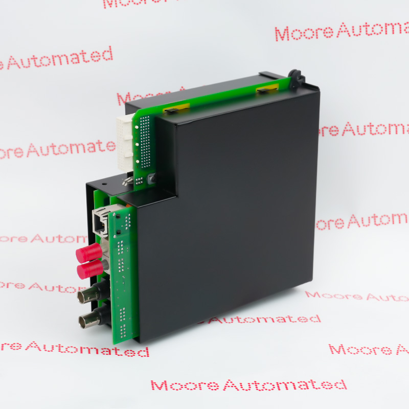
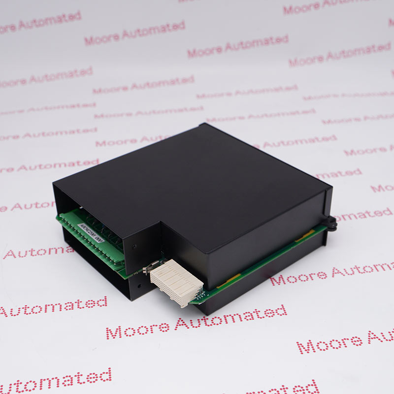
MIVII3000E00HI00 is the MIV II voltage-and-frequency relay configuration with a 10 to 250 V measuring range, English interface, and HI auxiliary supply.
Its protection functions can supervise motors, generators, lines, busbars, and automatic transfer applications. Metering, event recording, oscillography, and front-panel access support commissioning and fault analysis.
The ordering code confirms no conformal coating for this unit. Compatibility checks should include CT/VT wiring, auxiliary supply, output assignments, communications, protection settings, and breaker-control logic.
Model: MIVII3000E00HI00
Input range: 10 to 250 V
Auxiliary supply: 110–250 Vdc or 110–230 Vac
GE MIVII3000E00HI00 Official Manuals/Datasheets/Link
Use the official document to verify the ordering code, measuring range, auxiliary supply, relay outputs, communication ports, protection functions, environmental limits, and mechanical details before engineering or replacement.
Important Notice: Other accessories, manuals, cables, calibration data, software, etc. are not included with this equipment unless listed in the above stock item description. All prices are shown in USD.
Protection Functions
The MIV II 3000 function set combines phase undervoltage and overvoltage, ground overvoltage, and frequency protection in one compact digital relay. Independent pickup, timing, and logic settings allow the relay to support source supervision, load shedding, transfer schemes, and rotating-machine protection.
Breaker-control logic, configurable digital inputs, programmable outputs, event recording, and oscillography provide operational context beyond basic trip functions. All settings must be coordinated with the protected system and verified by qualified protection personnel.
Voltage measuring range: 10–250 V
Frequency elements: Two
Recorded data: Events and oscillography
Communication & Setup
The relay provides a front RS232 service port and a rear RS485 network port using Modbus RTU. The 2 x 16-character display, keypad, status LEDs, metering screens, and PC configuration software support setup and diagnostics.
Before installation, confirm the HI auxiliary-supply range of 110–250 Vdc or 110–230 Vac and match every terminal assignment to the project drawings. Verify programmable output logic, breaker status inputs, communication address, baud rate, and protection settings before placing the relay in service.
This MIV II ordering code has no conformal coating. Site temperature, humidity, panel sealing, wiring clearances, and electromagnetic environment should therefore be reviewed against the official ratings.