Get Repair Quote
Name
Company *
Phone *
Email *
Address
City
State / Province / Region
Zipcode
Country
Quantity *
Part Number *
Manufacturer
Preferred Condition
Additional Information
Cancel

IC694MDL660

Positive/Negative Logic Input Module
In Stock

Product Information:

PACSystems RX3i

24VDC 32-Point Positive/Negative

Logic Input Module

provides 32 discrete input points.

The inputs are positive or negative

logic inputs and will operate

at levels up to 30V.

Expand All
Collapse all

Technical specifications for IC694MDL660

  • Manufacturer:
    General Electric
  • Product Category:
    PLC System
  • Estimated shipping dimensions:
    3.5x13.5x13.5cm
  • Weight:
    0.36 kg
  • Tariff Code:
    8537101190
  • Country of origin:
    USA
  • Place of shipment:
    Xiamen, Fujian, China
  • Rated Voltage:
    24 volts DC
  • Input Voltage Range:
    0 to 30 volts DC
  • Inputs per Module:
    32 (four isolated groups of 8 inputs)
  • Isolation, Field to Backplane (optical):
    250 VAC continuous; 1500 VAC for one minute
  • Input Current:
    7.0 mA per point (typical) at rated voltage
  • Power Consumption:
    300mA (all inputs on) from 5 volt bus on backplane
  • Diagnostics:
    Terminal block presence reported to RX3i CPU
  • Category Series:
    PACSystems RX3i
  • Stock:
    30

Revisions

Revision Part #

Also known as

IC694MDL660BC
IC694MDL660-BC, Series BC, Rev BC
IC694MDL660CC
IC694MDL660-CC, Series CC, Rev CC
IC694MDL660EC
IC694MDL660-EC, Series EC, Rev EC

Information

Overview Manuals Principle

Features:

  • PACsystem RX3i 24 VDC Series
  • Positive/Negative Logic Input Module
  • This module is formerly produced by GE Intelligent Platforms
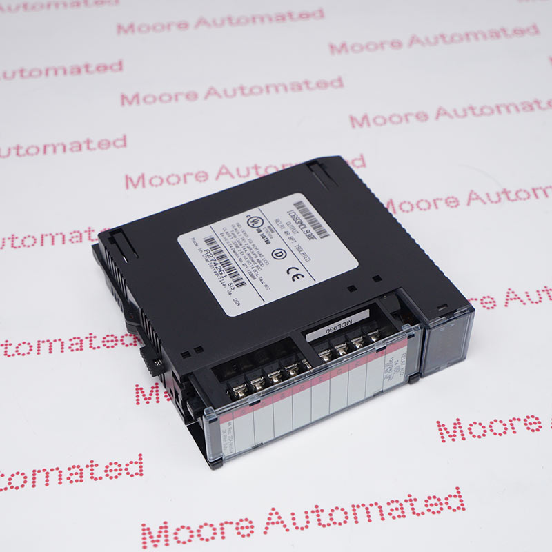
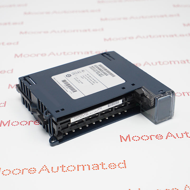
The IC694MDL660 is a component module in the PACSystem RX3i Programmable Automation Controller (PAC) family. Originally manufactured by GE Intelligent Platforms, it is now part of Emerson Automation. This module features a high-density 32-point input channel with group isolation, specifically comprising four input groups of eight channels each.

The IC694MDL660 is designed for an input signal voltage range of 0-30 VDC, with a nominal input voltage of 24 VDC and a rated input current of 7.0 mA per input point. The module's channel has a forward voltage range of 11.5-30 VDC and a cutoff voltage range of 0-5 VDC. The maximum forward current is 3.2 mA, and the maximum cutoff current is 1.1 mA.

The IC694MDL660 GENERAL ELECTRIC Positive/Negative Logic Input Module may still be available for purchase and support from Moore Automated Company beyond End-Of-Life (EOL) by the manufacturer (OEM).
GENERAL ELECTRIC IC694MDL660 Positive/Negative Logic Input Module datasheet(manual), Link Important Notice: Other accessories, manuals, cables, calibration data, software, etc. are not included with this equipment unless listed in the above stock item description. All prices are shown in USD.
This module requires high-density terminal blocks, specifically box-type terminal blocks (product number IC694TBB032) or spring-loaded terminal blocks (product number IC694TBS032). Each input channel is equipped with a dedicated input LED indicator to display the device's logic status. When the LED indicator is lit, it indicates logic 1, meaning the input channel is receiving input current; otherwise, the LED indicator is off.

Ask our team:

  • What input signal conditioning topology characterizes IC694MDL660 and how does IC694MDL660 ensure reliable 120 VAC discrete signal acquisition?
    The IC694MDL660 is engineered as a 120 VAC discrete input module incorporating opto-isolation and rectification circuitry to convert alternating current field signals into logic-level data recognizable by the PLC CPU. Through robust signal conditioning, IC694MDL660 ensures accurate state detection under industrial voltage conditions.
  • How does IC694MDL660 implement galvanic isolation to protect the RX3i backplane from high-voltage AC transients?
    The IC694MDL660 utilizes optically isolated input channels to electrically decouple field wiring from the backplane circuitry. This isolation architecture allows IC694MDL660 to mitigate voltage spikes, surge events, and electrical noise propagation.
  • What voltage threshold specifications define the ON/OFF state recognition parameters of IC694MDL660?
    The IC694MDL660 operates within defined AC voltage ranges to discriminate between logical high and low states. Adhering to these threshold values ensures that IC694MDL660 interprets field signals with precision and prevents ambiguous state detection.
  • How does IC694MDL660 address input filtering to suppress contact bounce and electrical interference?
    The IC694MDL660 integrates internal filtering mechanisms that attenuate transient fluctuations and short-duration disturbances. This filtering enhances signal integrity and prevents false triggering within IC694MDL660 during noisy industrial operations.
  • What channel grouping or common reference configuration is implemented in IC694MDL660, and how does IC694MDL660 manage common terminal wiring?
    The IC694MDL660 typically groups input channels with shared commons to simplify field wiring. Proper understanding of common terminal architecture ensures optimal installation and prevents cross-channel interference in IC694MDL660.
  • What diagnostic feedback mechanisms are available in IC694MDL660 to facilitate rapid fault isolation?
    The IC694MDL660 includes per-channel LED indicators that provide visual confirmation of input state. These diagnostics allow technicians to quickly validate wiring and operational status of IC694MDL660.
Quantity
Upload
(gif, jpg, jpeg, png, bmp, doc, docx, xls, xlsx, ppt, pdf, csv)
For more information on how your data is processed and stored by Moore automated please read our privacy policy.
Trusted by 5,000+ plants worldwide | Backed by our vast inventory of top-tier control parts, drives and servo motors, fast shipments are dispatched to cover your urgent needs. ABOUT US >>
Moore Disclaimer: Moore Automated's sales automation equipment and related solutions are intended for industrial automation and business operational efficiency improvement purposes only. Product information, technical parameters, and application cases are for reference only and do not constitute an absolute guarantee of performance for any specific industry, scenario, or final application. Actual equipment performance may vary depending on factors such as the usage environment, system integration method, and maintenance conditions. Users should confirm compatibility and safety based on professional technical assessments. Moore Automated assumes no liability for any direct or indirect losses caused by improper use, modification, or failure to operate according to specifications, to the extent permitted by law.