Registered Address: 32D Floor Guomao Building, No.388, Hubin South Road, Siming District, Xiamen,Fujian, China
ISO 9001:2015 Certified
Our quality management system covers sourcing,testing and dispatch
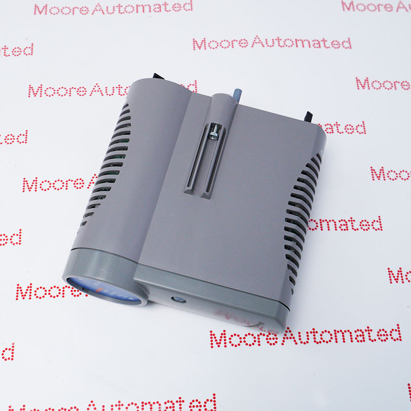
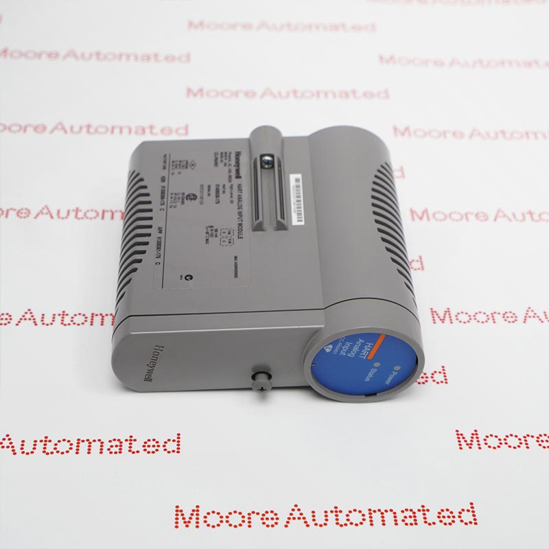
CC-PDIS01 51405042-175 is listed as a Honeywell Series C digital input sequence-of-events module. The CC-PDIS01 specification covers 32 discrete 24 V DC inputs and 1 ms event resolution. Normal and SOE modes use a 20 ms PV scan; low-latency operation uses 5 ms. Open-wire detection is available in Normal mode only. Match the full supplied marking, IOTA and installed configuration; the original specification does not decode the numeric -175 suffix.
Honeywell specifies CC-PDIS01 for discrete field-signal acquisition and sequence-of-events recording in Series C I/O. Its thirty-two inputs accept nominal 24 V DC signals within a documented DI power range of 18-30 V DC. Event time-tagging provides 1 ms resolution, while the PV scan follows the selected operating mode. The optical isolation rating is 1500 V AC RMS or ±1500 V DC with an input terminal referenced to common. These values describe different electrical and timing characteristics and must not be combined into an unsupported claim of 1 ms end-to-end response.
Configuration determines the available diagnostic behavior. Normal mode supports open-wire detection and marks the affected PV invalid when that fault is diagnosed. SOE mode retains a 20 ms PV scan, while Low Latency mode uses 5 ms; open-wire detection is not listed for those modes. Select the approved IOTA, field-power arrangement, signal polarity and any redundant pairing before commissioning. Retain the complete CC-PDIS01 51405042-175 marking in the replacement record. The reviewed original pages do not define the numeric suffix or prove interchangeability with other part-number revisions.
Choose Normal, Sequence of Events or Low Latency operation according to the control strategy. Normal and SOE modes scan the PV every 20 ms; Low Latency uses 5 ms. The 1 ms figure is event resolution, not the PV scan or a guaranteed whole-system response. Verify configured event recording and time order during commissioning.
Use a field-power source within 18-30 V DC. The documented ON threshold is at least 13 V DC or 3 mA; the OFF threshold is at most 5 V DC or 1.2 mA. Input impedance is 4.2 kilohms. Check contact leakage, cable resistance and source capability against these limits rather than assuming any nominal 24 V device is suitable.
Open-wire detection is documented for Normal mode only. A diagnosed open field wire is annunciated and causes the associated PV to be marked invalid. Confirm mode selection and the installed wiring arrangement before testing this function. Do not promise the same diagnostic in SOE or Low Latency mode, and follow the approved maintenance procedure for any fault simulation.
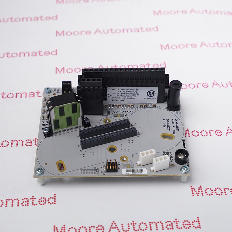
Select the IOTA for the approved standard, redundant or dedicated GI/IS configuration. The manufacturer lists CC-TDIL01 and CC-TDIL11 for standard nonredundant and redundant terminations, alongside separate GI/IS assemblies. Verify the chosen internal or external field-power arrangement and input indication polarity. Evaluate source voltage, contact leakage and field resistance against the ON and OFF thresholds. An IOTA's listed mounting length is not the module's net size or shipping dimension.
Before returning the channel to service, confirm whether the application requires Normal, SOE or Low Latency operation. Exercise approved input transitions and verify the indicated state, configured event recording and expected order. Keep the 1 ms SOE resolution separate from the 20 ms or 5 ms PV scan and the 5 ms ±20% filter/isolation delay. Where Normal-mode open-wire detection is used, verify the diagnostic and invalid-PV response under an authorized test procedure.



Registered Address: 32D Floor Guomao Building, No.388, Hubin South Road, Siming District, Xiamen,Fujian, China
MooreAutomated.com is the official website and primary online platform operated by Moore Automation Limited. The website provides information about the company’s industrial automation parts sourcing services, product coverage and customer support. Moore Automation Limited operates as an independent supplier and is not an authorized distributor or representative of the manufacturers displayed on this website unless expressly stated.