




Registered Address: 32D Floor Guomao Building, No.388, Hubin South Road, Siming District, Xiamen,Fujian, China
ISO 9001:2015 Certified
Our quality management system covers sourcing,testing and dispatch


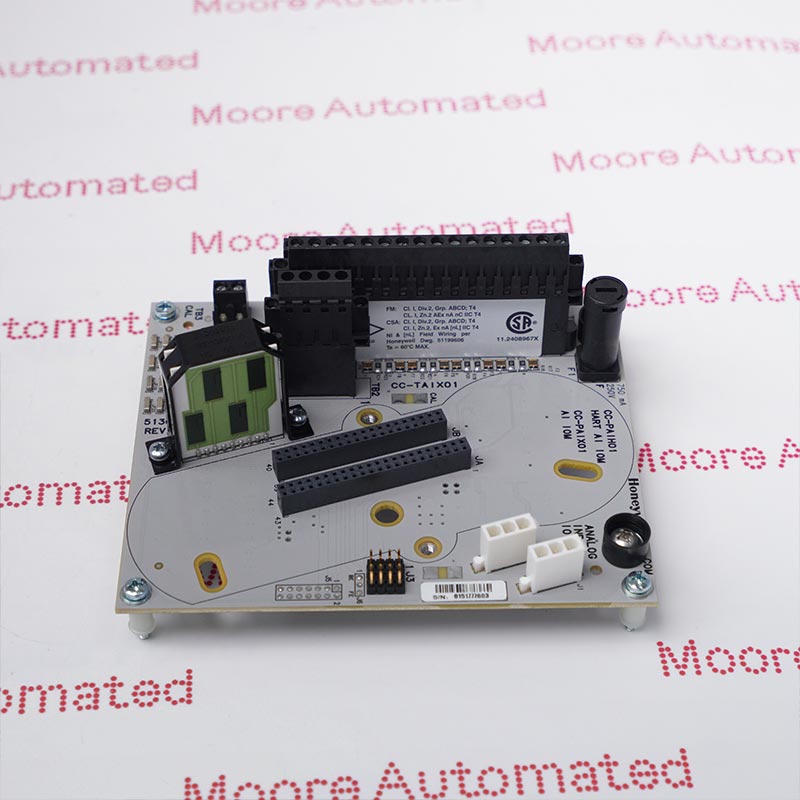
CC-TDIL01 51308386-175 is a Honeywell Series C nonredundant termination assembly for 32-channel, 24 V digital input installations. TB1 connects channels 1-16 and TB2 connects channels 17-32; TB3 selects the approved internal or external sense-power arrangement. The original guide shows the nine-inch IOTA and its field wiring. Input processing and isolation are provided by the compatible IOM, not by treating the termination board as a complete controller module.
The CC-TDIL01 board provides the field termination interface for a thirty-two-channel Series C digital input installation. The original connection tables divide the inputs into two groups of sixteen. TB1 positions 1-32 serve channels 1-16; TB2 repeats the screw numbering for channels 17-32. Odd-numbered screws carry channel power and even-numbered screws provide the corresponding return. Honeywell's selection table lists the nonredundant IOTA with CC-PDIL01 digital input and CC-PDIS01 sequence-of-events modules. Scan performance, optical isolation and event handling remain properties of the installed electronics and configuration, not independent ratings of this bare termination board.
The four-position TB3 block supports internal Honeywell 24 V sense power or an approved external supply. Its positions are internal positive, internal return, external positive and external return in that order. Preserve the documented jumper and return arrangement when exchanging a board; do not connect two supplies together simply because both are labelled 24 V. The guide describes current-limited protection for field shorts and a 22-kohm field resistor option for open-wire detection. Verify the actual field circuit and configured diagnostic response during commissioning. The nominal nine-inch board format must be distinguished from measured net dimensions and protective-package dimensions.
TB1 covers inputs 1-16 and TB2 covers inputs 17-32. Both terminal blocks use positions 1-32 locally, with power on odd-numbered screws and returns on the following even-numbered screws. Preserve both the block designation and channel number on wire labels; a screw number without TB1 or TB2 does not uniquely identify the field input.
TB3 position 1 is internal +24 V, position 2 internal return, position 3 external +24 V and position 4 external return. The original diagrams distinguish the internal jumper arrangement from external supply wiring. A qualified technician must confirm the selected source, polarity and return path before energizing the installation; matching nominal voltage alone is insufficient.
Honeywell shows an optional 22-kohm resistor in the field circuit to permit open-wire detection. Its placement must follow the original diagram and the installed input-module configuration. This is not a claim that every connected dry contact automatically provides wire-break diagnostics. Check the resulting input quality and alarm response with the approved commissioning procedure.
Use the installed input-module type to determine the required signal processing and event behavior. The selection table lists both standard digital input and sequence-of-events electronics against this IOTA, but a termination board alone does not create time-stamped event capability. Check the TB1/TB2 channel labels, contact circuit and power-return path before transferring wiring. Prove the channel identity and configured normal state after installation, particularly where the application reports equipment status or maintenance alarms.
Record the existing TB3 arrangement before disconnecting the board. The guide provides distinct wiring for internal Honeywell sense power and external field power, and describes current limiting for field short circuits. After replacement, inspect the connectors and supply polarity, then test the intended input states using the site's authorized procedure. Where the optional 22-kohm open-wire circuit is installed, verify wire-break indication and the control strategy's response; resistor presence alone is not a completed diagnostic test.

Registered Address: 32D Floor Guomao Building, No.388, Hubin South Road, Siming District, Xiamen,Fujian, China
MooreAutomated.com is the official website and primary online platform operated by Moore Automation Limited. The website provides information about the company’s industrial automation parts sourcing services, product coverage and customer support. Moore Automation Limited operates as an independent supplier and is not an authorized distributor or representative of the manufacturers displayed on this website unless expressly stated.