



Registered Address: 32D Floor Guomao Building, No.388, Hubin South Road, Siming District, Xiamen,Fujian, China
ISO 9001:2015 Certified
Our quality management system covers sourcing,testing and dispatch


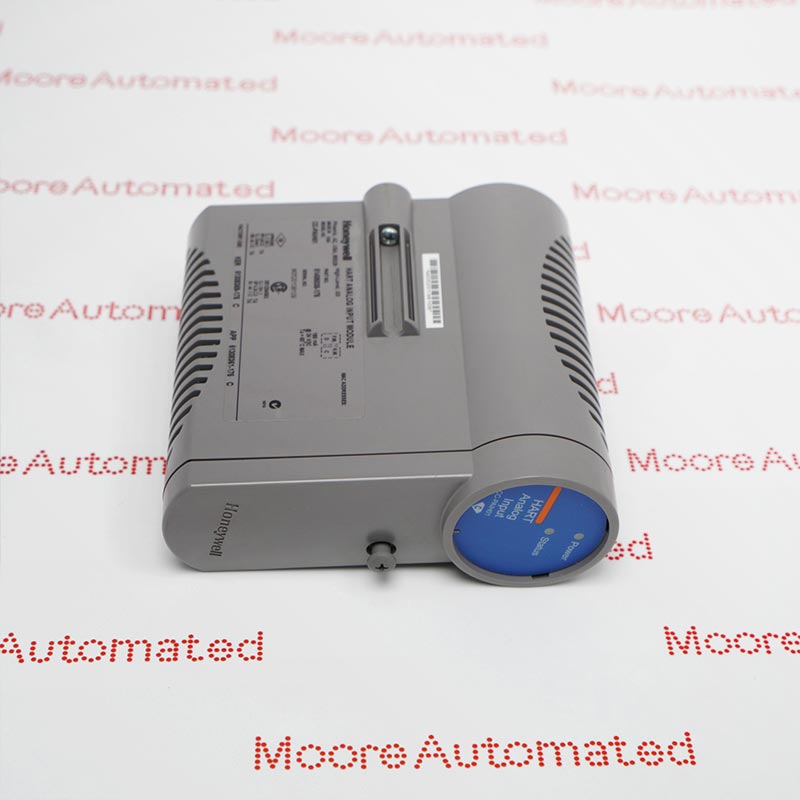
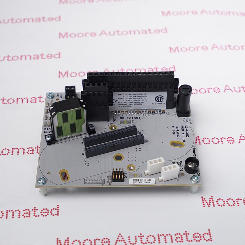
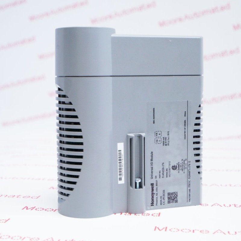
CC-TUIO41 51306873-176 is listed as a Honeywell Series C redundant UIO-2 termination assembly. The coated CC-TUIO41 board provides 32 field-channel connections, two positions for matched CC-PUIO31 modules and a separate four-position +24 V terminal block. It is not a cable or a standalone signal-processing module. Match the complete board number and revision to the installed system; the reviewed original sources do not decode the numeric -176 suffix.
The CC-TUIO41 IOTA connects field wiring to the redundant UIO-2 electronics rather than acting as an interconnection cable. Honeywell's Series C guide pairs this coated board with CC-PUIO31 modules and shows a twelve-inch redundant layout. TB1 carries channels 1-16 and TB2 carries channels 17-32, each with the documented return and power screw pair. TB3 adds four +24 V screw positions. Module mounting, field wiring and supplied terminal components should therefore be checked separately when defining the replacement assembly.
The paired UIO-2 system can use individual channels for analog current input, analog current output, digital input or digital output. The installation guide permits compatible two-, three- and four-wire current transmitters, with 0-20 mA or 4-20 mA analog input and 4-20 mA analog output. It explicitly excludes direct voltage, thermocouple, RTD and NAMUR inputs without appropriate external interfacing. Select the correct mode and power arrangement for every loop. Retain the complete 51306873-176 board marking and revision; neither a similar connector layout nor a different numeric suffix proves interchangeability.
Use the coated CC-TUIO41 redundant IOTA with the documented CC-PUIO31 module arrangement. The board and IOMs perform different functions and are separate supply items. Confirm the receiving hardware, approved system release and redundant configuration. A first-generation UIO board or the smaller nonredundant UIO-2 IOTA is not an automatic mechanical or functional replacement.
The redundant IOTA terminal table assigns channels 1-16 to TB1 and channels 17-32 to TB2. Each channel has the specified return and power screw pair. TB3 positions 1 through 4 are labelled +24 V. Verify terminal labels and circuit drawings before reconnection; these four power positions are not four additional process channels.
With compatible UIO-2 electronics, analog-input channels accept 0-20 mA or 4-20 mA current signals from appropriately powered devices. Analog outputs use 4-20 mA. Direct voltage, thermocouple, RTD and NAMUR inputs are outside the documented AI interface. Use an approved external converter or interface where required, and verify loop power, polarity and selected IOM mode together.
Identify the two UIO-2 module positions and check that the installed IOMs and IOTA belong to the same approved hardware arrangement. Keep the TB1 and TB2 channel groups separate from the TB3 power connections when recording wiring. Inspect terminal plugs, board marking and mounting provisions before replacement, and define which components are included in the supply. A quotation for the IOTA alone does not include a pair of electronic modules unless expressly stated.
Document each connected channel's mode, loop power and field device before maintenance. Validate current-input scaling, current-output behavior and discrete-state indication with the installed UIO-2 configuration. Where digital-input open-wire detection is configured, the guide calls for an appropriate field resistor near the switch contact. A configured digital-output channel can supply up to 0.5 A under the system's applicable conditions; do not infer that all possible loads can be driven simultaneously without checking the full power design.

Registered Address: 32D Floor Guomao Building, No.388, Hubin South Road, Siming District, Xiamen,Fujian, China
MooreAutomated.com is the official website and primary online platform operated by Moore Automation Limited. The website provides information about the company’s industrial automation parts sourcing services, product coverage and customer support. Moore Automation Limited operates as an independent supplier and is not an authorized distributor or representative of the manufacturers displayed on this website unless expressly stated.