
Registered Address: 32D Floor Guomao Building, No.388, Hubin South Road, Siming District, Xiamen,Fujian, China
ISO 9001:2015 Certified
Our quality management system covers sourcing,testing and dispatch
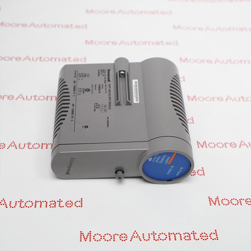
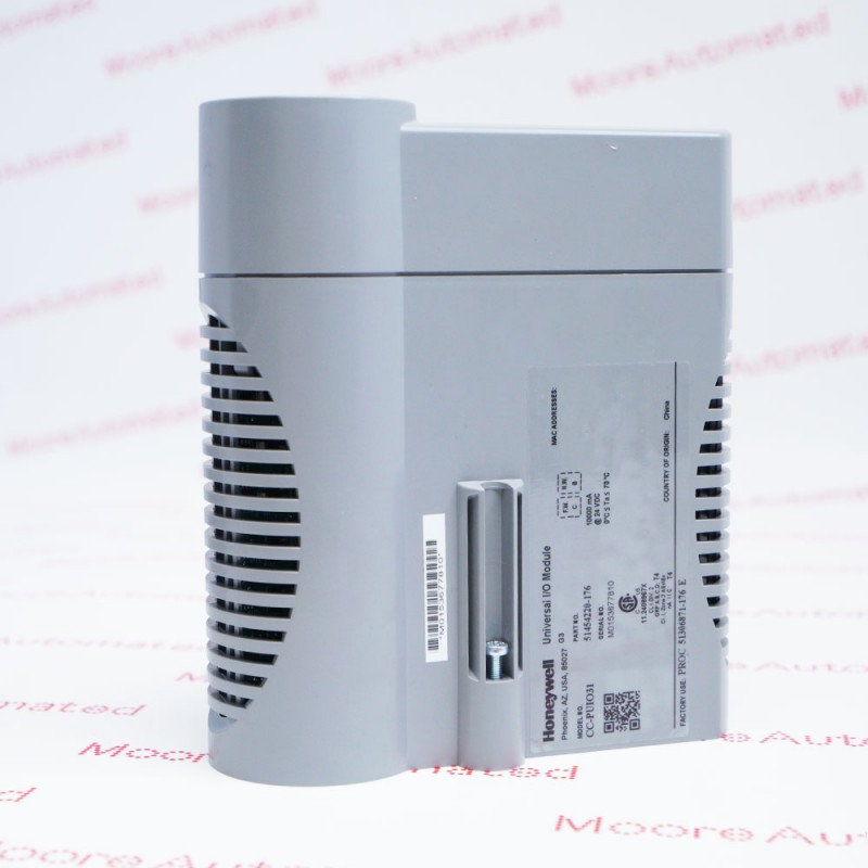
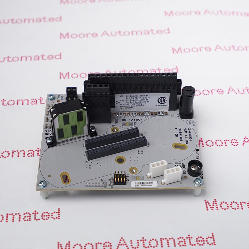
CC-TUI041 is Honeywell's redundant UIO-2 termination assembly, listed in the Universal Process Cabinet guide and shown as CC-TUIO41 in the Series C I/O guide. The coated IOTA provides field terminals and mounting positions for the matched universal I/O modules, with 32 channel connections divided between TB1 and TB2. Input/output processing and channel-mode configuration belong to the installed IOMs, not to the termination board alone.
The CC-TUI041 provides the field-side interface for a redundant Honeywell UIO-2 installation. Honeywell's Universal Process Cabinet guide identifies it as a redundant UIO2 IOTA, while the Series C guide uses the CC-TUIO41 designation for the coated redundant assembly paired with CC-PUIO31. Its terminal arrangement covers 32 channels rather than four analog inputs: TB1 carries channels 1–16 and TB2 carries channels 17–32. Two module positions support the redundant hardware arrangement, and TB3 supplies the documented additional +24 V connection points.
Universal I/O does not mean that every sensor can be connected directly. With the matching UIO-2 modules, channels can be configured for analog current input, analog current output, digital input or digital output. The guide supports 0–20 mA or 4–20 mA analog inputs and explicitly excludes direct voltage, thermocouple, RTD and NAMUR inputs without suitable external interfacing. Check each loop's selected mode, transmitter power requirements and terminal assignment before applying power, and treat the module configuration and termination-board identity as separate verification items.
The Series C guide identifies the coated redundant UIO-2 IOTA as CC-TUIO41 and pairs it with CC-PUIO31; the UPC component list writes the IOTA designation as CC-TUI041. The redundant board has two IOM mounting positions. Verify the complete board and module labels and the required system release. The IOTA is not itself a universal input/output processing module.
TB1 terminates channels 1–16 and TB2 terminates channels 17–32, using the documented return and power screw pair for each channel. TB3 has +24 V connections at screw positions 1 through 4. Use the redundant IOTA drawing and terminal tables for the actual board revision; do not transplant the wiring assignments from the smaller non-redundant assembly.
UIO-2 analog inputs accept 0–20 mA or 4–20 mA current signals, and analog outputs drive 4–20 mA. A configured digital-output channel can supply up to 0.5 A under the applicable module conditions. Direct voltage, thermocouple, RTD and NAMUR inputs are not supported by the documented AI interface. Match external conversion, loop power and channel configuration to the field device before commissioning.
For a replacement enquiry, provide the complete board marking and revision together with the labels of the installed UIO-2 modules. The CC-TUI041 wording in the UPC parts list and CC-TUIO41 wording in the Series C guide should be reconciled against the supplied hardware, not used to ignore a different suffix or assembly number. Confirm that the required position is the redundant arrangement and whether both IOMs are retained, replaced or supplied separately.
Define the supply boundary before ordering: the IOTA, the removable terminal components and the electronic IOMs are distinct items. State which terminal plugs, mounting parts and cables must be included and which will be reused from the installed cabinet. A quotation for a redundant IOTA should not be read as an offer for two IOMs or a complete cabinet. Provide the cabinet position and wiring drawing where terminal layout or accessory scope is uncertain.

Registered Address: 32D Floor Guomao Building, No.388, Hubin South Road, Siming District, Xiamen,Fujian, China
MooreAutomated.com is the official website and primary online platform operated by Moore Automation Limited. The website provides information about the company’s industrial automation parts sourcing services, product coverage and customer support. Moore Automation Limited operates as an independent supplier and is not an authorized distributor or representative of the manufacturers displayed on this website unless expressly stated.