Overview
Manuals
How It Works
Core Application Scenarios
Features:
- Allows field engineers to adjust or commit specific operational safety parameters directly to the module firmware
- Provides a hard reset command mechanism to clear system faults or trip memories once a safe state is re-established or testing concludes
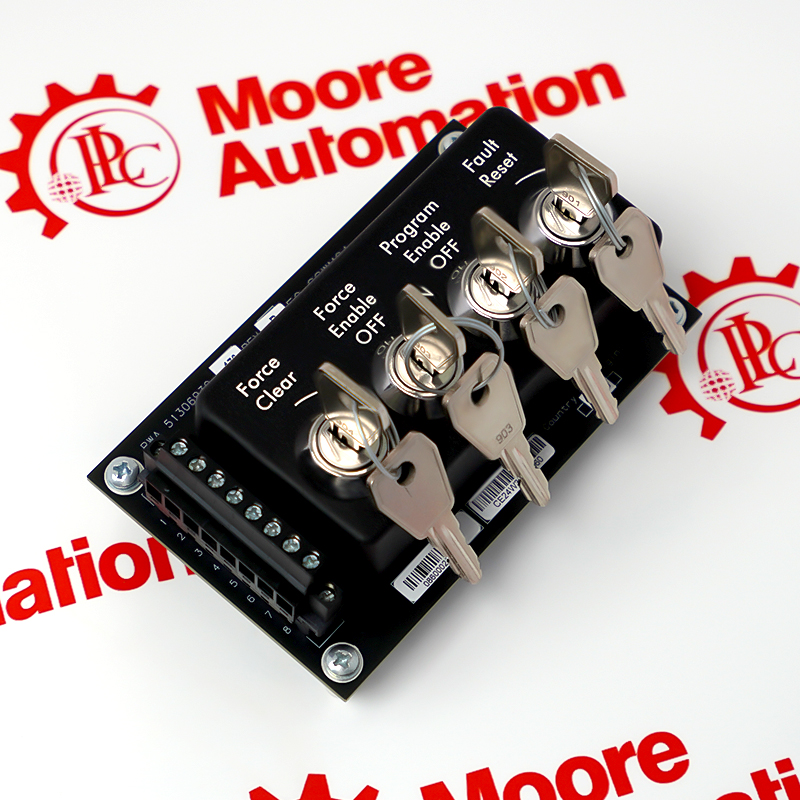
- Industrial-grade Safety Control (SC) Switch Module engineered for integration within the Honeywell Safety Manager SC system framework
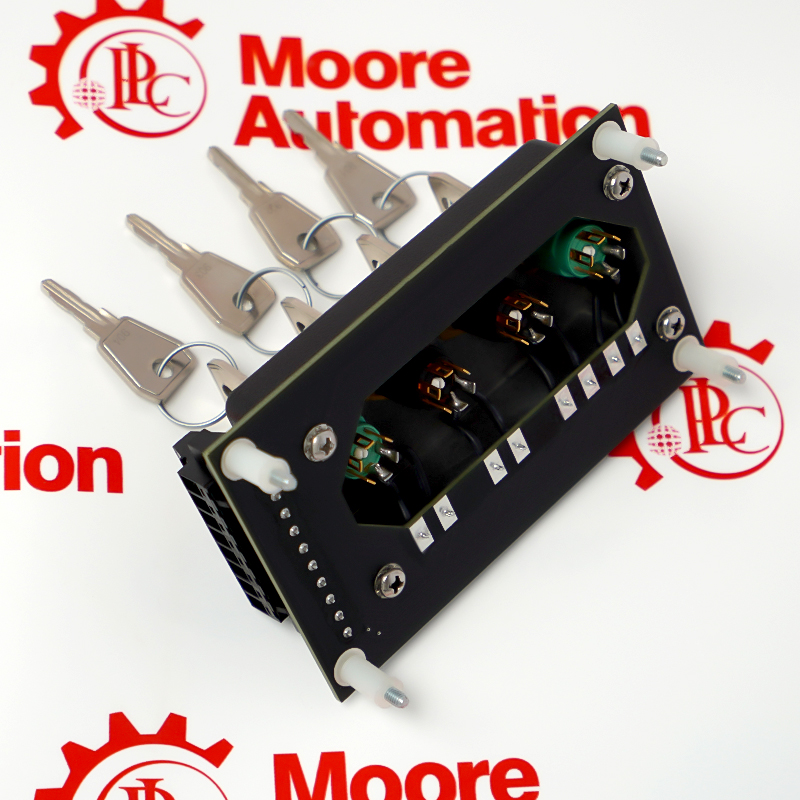
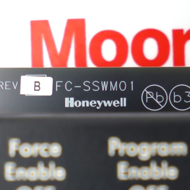
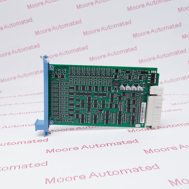
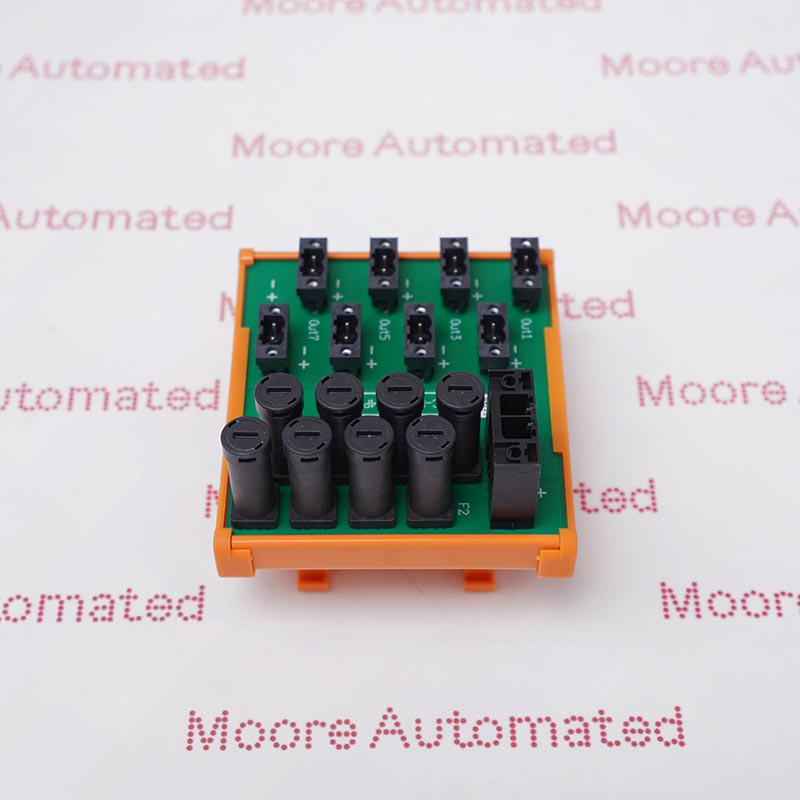
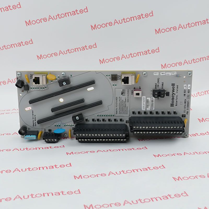
The FC-SSWM01 (part number: 51306930-176) is a dedicated programmable/force/reset switch module in Honeywell's next-generation Safety Manager SC critical safety control platform. It plays a core auxiliary role in the distributed safety instrumented system (SIS) for safety status control and hard logic interaction.
During the safety configuration phase, this module can be programmed and connected at the hardware level via specific software modes. During system testing or routine troubleshooting, field engineers can utilize the physical channel's safety forced setting function to temporarily bypass or simulate certain input/output signals to verify the logic performance of the controlled loop. In the event of a sudden failure, safety interlock activation, or emergency stop (ESD) response, its provided hard logic reset button interface can serve as a critical hardware path, guiding the entire plant back from a safe state to normal production.
The FC-SSWM01 Honeywell Safety Control (SC) switch module may still be available for purchase and support from Moore Automated Company beyond End-Of-Life (EOL) by the manufacturer (OEM).
Honeywell FC-SSWM01 Safety Control (SC) switch module INFO(Datasheets), Link
Important Notice: Other accessories, manuals, cables, calibration data, software, etc. are not included with this equipment unless listed in the above stock item description. All prices are shown in USD.
The FC-SSWM01 employs high-speed electrical isolation sampling and a bidirectional interlocking status feedback mechanism, utilizing physical hard contact signals for operation. When the physical key on the control cabinet or operator panel is rotated or the reset button is closed, the module's eight digital input (DI) channels acquire real-time DC level changes (operating voltage 12V to 24V DC) and perform electrical isolation conversion via internal optocouplers. Within a rapid response time of less than 10ms, the operating status is transmitted to the C-series main processor of the safety system (e.g., FC-SCNT02).
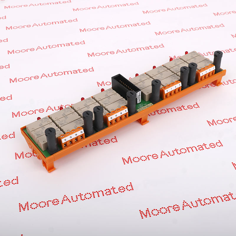
The processor analyzes the physical inputs in real-time according to built-in highest-priority safety rules. If a valid forced or reset command is detected, the module immediately drives its eight onboard high-capacity single-pole double-throw relays to close (switching capacity up to 5A @ 24V DC), directly closing or opening the power circuits of external safety actuators (e.g., solenoid valves and circuit breaker trip coils) at the hardware level, thus fully executing the safety command.
During this process, its built-in microcontroller chip continuously performs open/short-circuit pulse self-tests on the relay contacts and field cables. Once an external link failure is detected, it immediately sends an alert to the Experion PKS via the upper-layer network to ensure the absolute security and reliability of operational commands.
Loop Testing and Commissioning: Used during factory maintenance or initial system setup to safely verify that field instruments (e.g., valves and transmitters) trigger the correct logical response.
Controlled Logic Bypass: Allows engineers to force input or output states to fixed values. This is crucial for maintaining faulty field sensors without triggering the entire process loop.
System Reset After Trip: A dedicated physical mechanism to clear locked safety alarms and reset safety loops after the process hazard has been completely eliminated.