Overview
Manuals
Principle
Core Application Roles
Features:
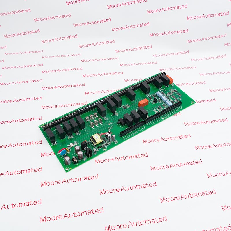
- Control Board Circuit Board
- Hardware Pushbuttons for Harsh Environments
- Unified Touchscreen for all Motortronics Products
The MVC4-TCB 36-0576 features robust, shock-resistant terminals and structured isolation channels, enhancing electrical integrity, reducing the risk of signal crosstalk, and providing a safe, ergonomic operating experience for operators and maintenance personnel. This modular design also allows for quick circuit replacement or expansion without disrupting the entire system.
Another key feature of the MVC4-TCB 36-0576 is its support for efficient system diagnostics and maintenance. With clearly marked terminals and standardized connection points, engineers can quickly identify circuit paths, isolate faults, and perform preventative maintenance. Its compatibility with multi-axis motor systems and distributed control architectures allows for seamless integration into complex industrial environments, delivering stable performance even under vibration, temperature fluctuations, and other harsh operating conditions.
The MVC4-TCB 36-0576 Motortronics Control Board Circuit Board may still be available for purchase and support from Moore Automated Company beyond End-Of-Life (EOL) by the manufacturer (OEM).
Motortronics MVC4-TCB 36-0576 Control Board Circuit Board datasheet(manual), Link
Important Notice: Other accessories, manuals, cables, calibration data, software, etc. are not included with this equipment unless listed in the above stock item description. All prices are shown in USD.
The MVC4-TCB 36-0576 works by establishing a reliable electrical path between connected devices. Signals from motor controllers or sensors are transmitted through conductive contacts on the terminal blocks, while insulating barriers and mechanical isolation ensure signal integrity and operator safety. Its modular design enables efficient signal routing, allowing control commands and feedback measurements to flow seamlessly between the motor control unit and the connected automation network, thereby ensuring coordinated operation and real-time monitoring of motor performance.
User Interface and Connectivity: Serves as the central interface for all user terminals, including input, control power connections, and output relays.
Motor Protection Integration: Handles “real thermal model” signals, providing advanced protection against motor overload, phase loss, and imbalance.
HMI System Bridging: Connects the soft starter to the Msmart touchscreen system, enabling users to monitor performance data such as starting current and RTD temperature.
External Device Coordination: Includes dedicated timing relays for connection to power factor correction (PFC) contactors and other peripheral devices.