Overview
Manuals
Main Features
Primary Application
Features:
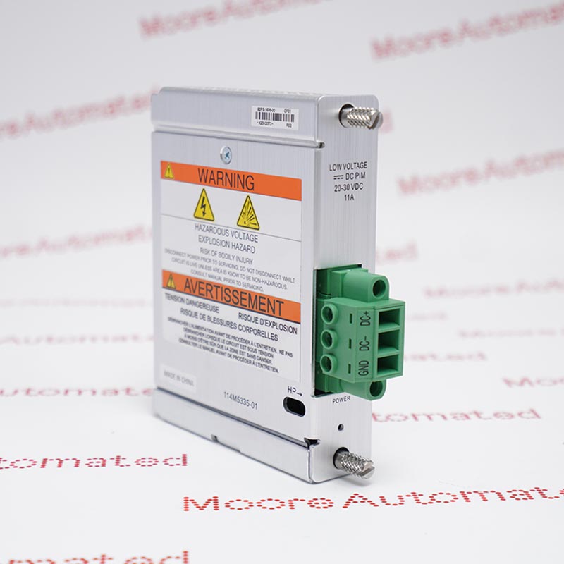
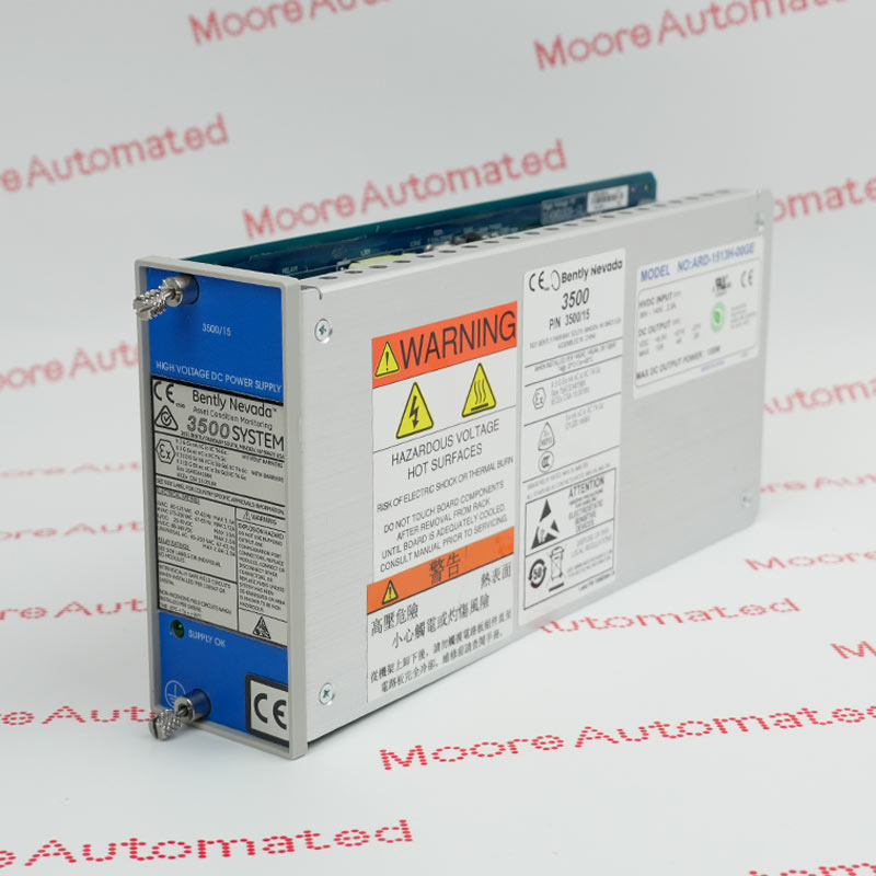
- High Voltage DC Power Supply
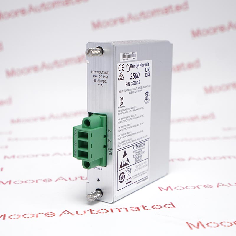
- 3500/15 AC and DC Power Supplies
- Uses the High Voltage DC Power Supply and the High Voltage DC Power Input Module (PIM)
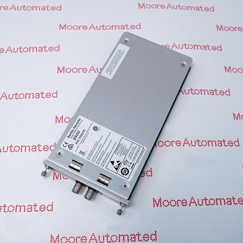
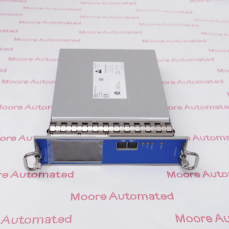
The Bently Nevada 3500/15 AC and DC Power Supplies are half-height modules and must be installed in designated slots on the left side of the rack. The 3500 rack can contain one or two power supplies with any combinations of AC and DC. Either supply can power a full rack.
When two power supplies are installed in a rack, the one in the lower slot acts as the primary supply, and the other in the upper slot acts as the backup supply. If installed, the second supply is the backup for the primary one. Removing or inserting either power supply module does not disrupt operation of the rack as long as a second power supply is installed.
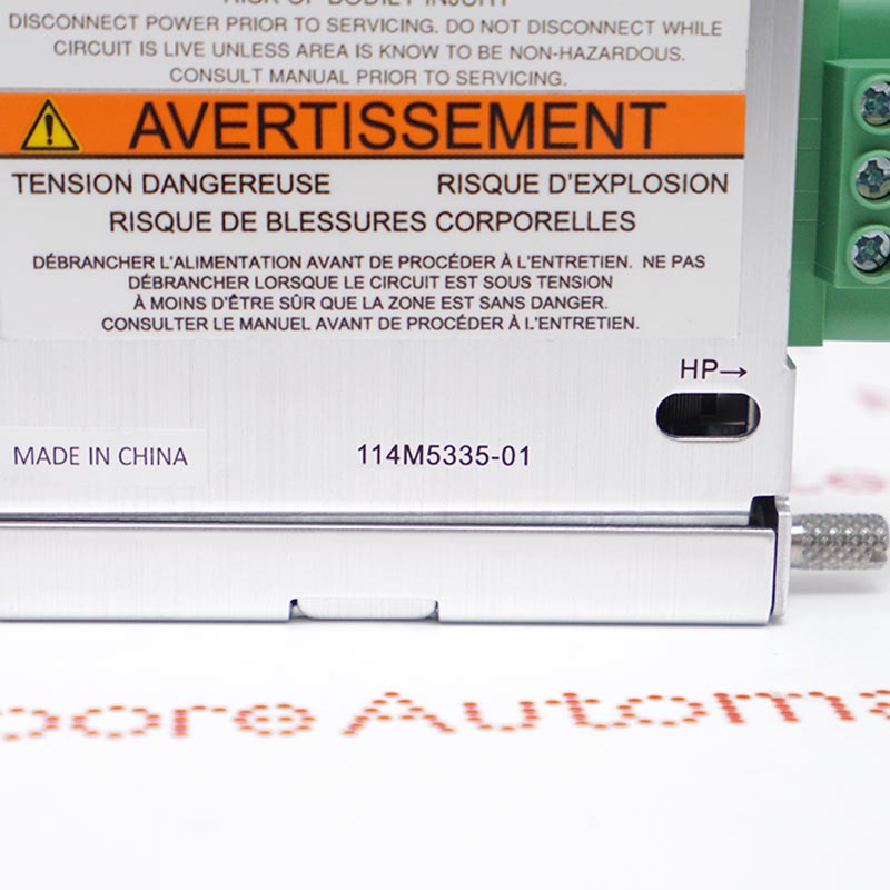
The 114M5335-01 Bently Nevada Low Voltage DC PIM may still be available for purchase and support from Moore Automated Company beyond End-Of-Life (EOL) by the manufacturer (OEM).
Bently Nevada 114M5335-01 Low Voltage DC PIM Manuals(Datasheets), Link
Important Notice: Other accessories, manuals, cables, calibration data, software, etc. are not included with this equipment unless listed in the above stock item description. All prices are shown in USD.
The 3500/15 AC and DC Power Supplies accepts a wide range of input voltages and converts them to voltages acceptable for use by other 3500 modules. The following power supplies are available with the 3500 Series Machinery Protection System:Universal AC Power/High Voltage DC Power Supply/Low Voltage DC Power Supply
- Field Wiring Interface: It serves as the physical connection point for a 20 to 30 VDC external power supply.
- Redundant Power Configuration: In mission-critical environments such as oil and gas facilities or power plants, two Power Interface Modules (PIMs) are typically used—one for the primary power supply and one for the backup power supply.
- System Protection: It includes a backup fuse (typically a 5A fast-blow fuse) to protect the rack-mount backplane from external overvoltages or short circuits.