Overview
Manuals
Principle
Applications
Functionality
Features:
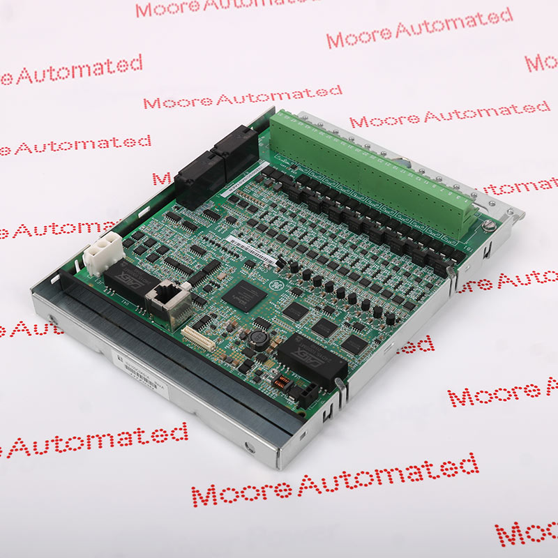
- GE Gas Exciter ISBus Board EX2100 Excitation Control
- Mark VIe & Mark VIeS Control Systems
- Mark VI IS200 Series produced by General Electric
High-performance control processor module designed specifically for the Mark VIe distributed control system platform. Its primary functions are executing control logic, sequential management, and real-time data processing, making it suitable for industrial automation and power generation applications. As the central processing unit in the control architecture, the module coordinates communication between I/O modules, field devices, and monitoring systems to ensure stable and deterministic system operation.
It can handle critical tasks such as signal processing, alarm management, system diagnostics, and fault handling, while maintaining synchronized operation among distributed controllers. Its industrial-grade design allows it to be deployed in demanding environments such as turbines, power plants, and process control facilities where real-time performance and system integrity requirements are extremely high.
The IS200TRPGH2B GENERAL ELECTRIC Primary Trip Terminal Board may still be available for purchase and support from Moore Automated Company beyond End-Of-Life (EOL) by the manufacturer (OEM).
GENERAL ELECTRIC IS200TRPGH2B Primary Trip Terminal Board info(manual), Link
Important Notice: Other accessories, manuals, cables, calibration data, software, etc. are not included with this equipment unless listed in the above stock item description. All prices are shown in USD.
This module receives analog and/or digital input signals from connected sensors or subsystems, performs signal isolation, filtering, and level conversion via onboard circuitry, and then transmits the processed data to the central controller via a high-speed backplane or internal communication bus. Simultaneously, it parses control commands from the main processor and distributes corresponding output signals to relevant field devices or subordinate modules. All of this is achieved through coordinated data exchange, electrical isolation, and embedded firmware logic.
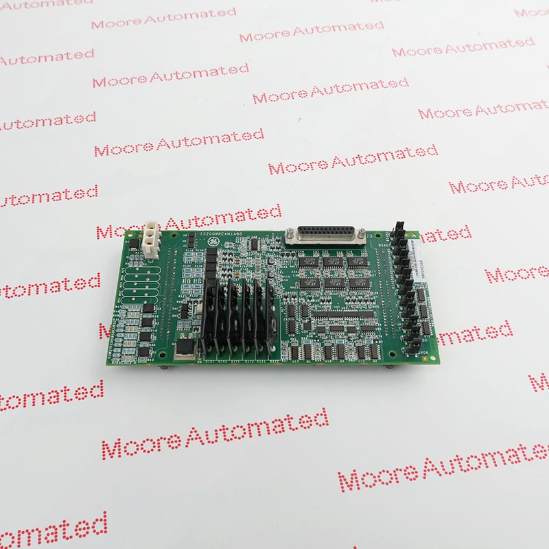
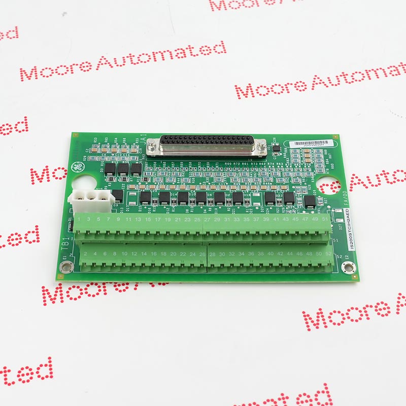
1. Gas Turbine Protection: The primary function of this circuit board is to achieve emergency shutdown (tripping) of the gas turbine by operating three trip solenoid valves (ETDs).
2. Flame Detection: This circuit board integrates and processes input signals from up to eight Geiger-Miller flame detectors. It converts the detector's energy into voltage pulses to measure flame intensity, which is crucial for the safe operation of the gas turbine.
3. Simplex Control System: Unlike the H1A/H1B versions (which use three relays for tri-multiplexed voting per solenoid valve), the H2A/H2B versions are designed for simplex (single controller) applications, using only one relay per trip solenoid valve.
4. Interface with TREG Board: The TRPG works in conjunction with the TREG (Emergency Trip) board to establish a complete master and emergency interface; the TREG provides the positive terminal for DC power, while the TRPG provides the negative terminal for the solenoid valve.
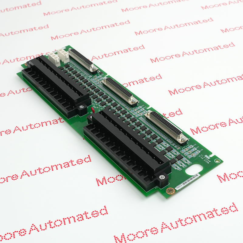
1. Trip Solenoid Valve Interface: This interface contains three relays and can directly connect to up to three trip solenoid valves (electric trip devices or ETDs).
2. Relay Operation: When an I/O module (e.g., VTUR or PTUR) controls these relays to operate the main solenoid valve, the main trip function is executed, thereby cutting off the fuel or steam supply to the turbine.
3. Simplex Function: Unlike the H1 version, which has three relays per solenoid valve for Triple Module Redundancy (TMR), the H2B version is designed for simplex applications, with only one relay per trip solenoid valve.
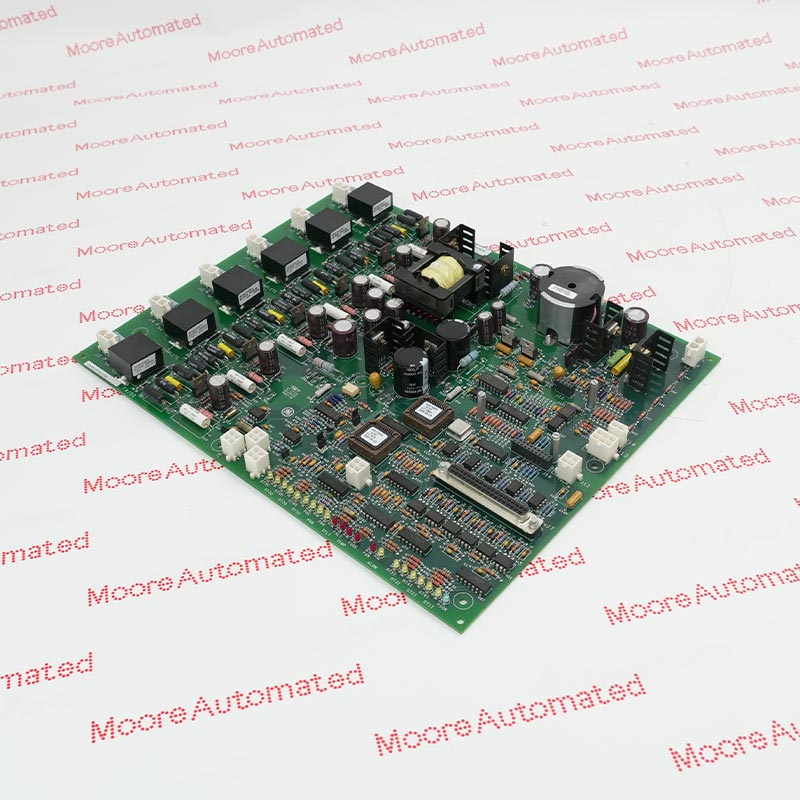
4. Flame Detector Input: This interface can process signals from up to eight Geiger-Miller flame detectors.
5. Signal Conversion: This board converts the energy from these detectors into voltage pulses. The rate of these pulses (ranging from 0 to 1000 pulses per second) is used to measure flame intensity.
6. Logic processing: Pulses exceeding 2.5 volts are interpreted as logic high levels, and their frequency is measured at 40-millisecond intervals to confirm the presence of a flame.