

Registered Address: 32D Floor Guomao Building, No.388, Hubin South Road, Siming District, Xiamen,Fujian, China
ISO 9001:2015 Certified
Our quality management system covers sourcing,testing and dispatch

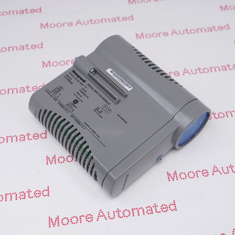
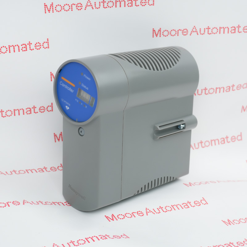
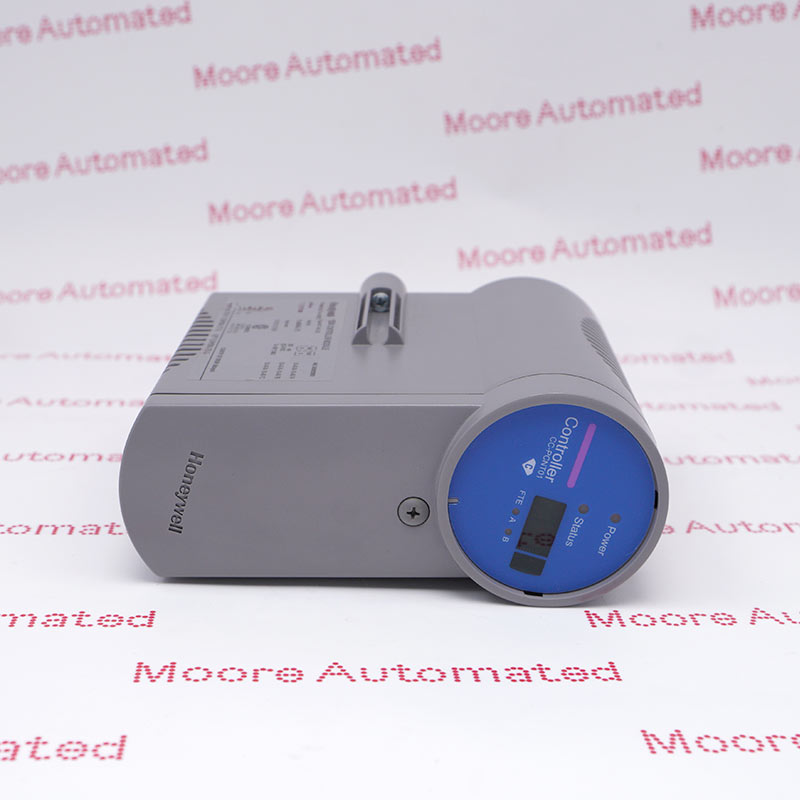
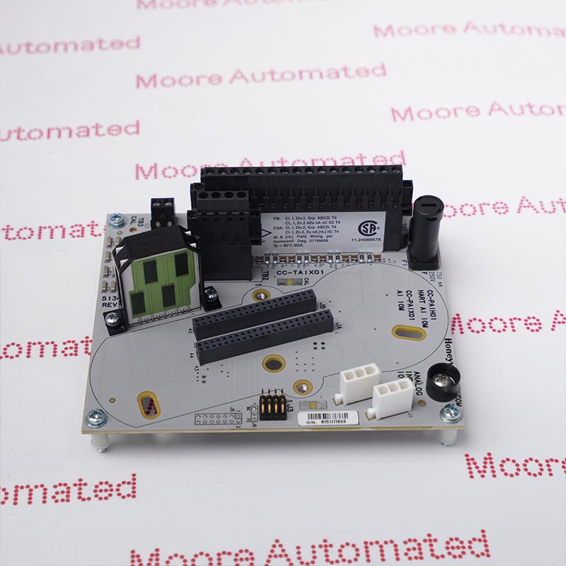
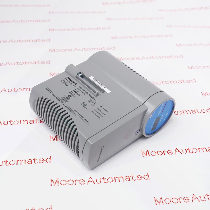
CC-TDOR01 is the nonredundant Series C digital-output relay IOTA, identified by Honeywell as coated assembly 51308376-175. It supports the CC-PDOB01 output module and connects to the separate relay-extension hardware for isolated dry-contact outputs. The published switching ratings apply to the complete matched relay arrangement, not to the termination board alone.
The CC-TDOR01 is the nonredundant termination assembly in Honeywell's Series C relay-output configuration. It provides the interface for a CC-PDOB01 output module and the connection to the relay-extension hardware, rather than acting as an independent controller or a complete bank of field relays. Honeywell identifies the coated IOTA by assembly number 51308376-175 and a nominal 6-inch size. The associated relay arrangement delivers 32 isolated output contacts, with the required normally open or normally closed behavior selected separately for each channel.
Load selection is an essential part of applying this assembly. The documented relay contacts support up to 3 A at 125 or 250 VAC for resistive duty, but the allowable DC current falls as voltage rises, and inductive duty has separate limits. Check both the steady-state load and any starting or switching surge before connecting equipment. Record the existing jumpers, IOM identity, relay-extension connection and field-circuit labels before replacement, then verify commanded states and contact behavior using the approved installation and commissioning procedure.
Match the switched load to the applicable relay rating. Resistive limits are 3 A at 125/250 VAC, 3 A at 30 VDC, 1 A at 48 VDC and 0.2 A at 125 VDC. For inductive AC duty, the stated limit is 2 A at 125/250 VAC with a 0.4 power factor. Check the full specification for other load conditions; the maximum load voltage is not a promise that every listed current is permitted at that voltage.
The complete relay arrangement provides 32 isolated contacts. A channel jumper selects Form A (SPST, normally open) or Form B (SPST, normally closed) operation. Record the installed settings and confirm the intended de-energized contact state before maintenance. A relay contact choice does not by itself establish a safety-rated function or replace the plant's interlock design and validation.
The nonredundant CC-TDOR01 IOTA is listed with CC-PDOB01 and the separate CC-SDOR01 relay extension. Its nominal 6-inch size differs from the 12-inch redundant CC-TDOR11 arrangement. Inspect the actual IOTA label and relay-extension connection, and specify whether the order requires only the IOTA or additional hardware. Similar signal functions do not make the redundant and nonredundant assemblies direct substitutes.
For a resistive load, compare the operating voltage and steady current with the corresponding AC or DC line in the relay specification. The maximum inrush figure is 10 A for four seconds at a ten-percent duty cycle; it must not be used as a continuous-current rating. Inductive loads require their own assessment and suitable protection under the equipment design. The published minimum load is 12 VDC and 100 mA, so very small signal circuits need particular attention rather than an assumption that any dry-contact application is suitable.
Honeywell specifies 1500 VAC RMS or ±1500 VDC isolation between relay channels and between a channel and logic common, with maximum turn-on and turn-off times of 20 ms. These ratings belong to the complete matched relay arrangement. After replacing the IOTA or reconnecting the extension, verify channel identification, selected NO/NC behavior and the response of each affected field circuit. Preserve the existing circuit protection and separation requirements; do not treat the isolation test figure as a permissible operating load voltage.
CC-TDOR01 is documented in Honeywell's December 2021 Series C specification and November 2019 user guide. A current exact-model OEM lifecycle notice has not been verified, so this page does not assert an active, discontinued or end-of-support status.
Moore Automated confirms the available assembly, supplied condition and allocation in the quotation. CC-TDOR11 is a separately documented redundant arrangement, not an asserted drop-in successor; any replacement requires review of the installed IOM, termination and relay-extension configuration.

Registered Address: 32D Floor Guomao Building, No.388, Hubin South Road, Siming District, Xiamen,Fujian, China
MooreAutomated.com is the official website and primary online platform operated by Moore Automation Limited. The website provides information about the company’s industrial automation parts sourcing services, product coverage and customer support. Moore Automation Limited operates as an independent supplier and is not an authorized distributor or representative of the manufacturers displayed on this website unless expressly stated.