

Registered Address: 32D Floor Guomao Building, No.388, Hubin South Road, Siming District, Xiamen,Fujian, China
ISO 9001:2015 Certified
Our quality management system covers sourcing,testing and dispatch
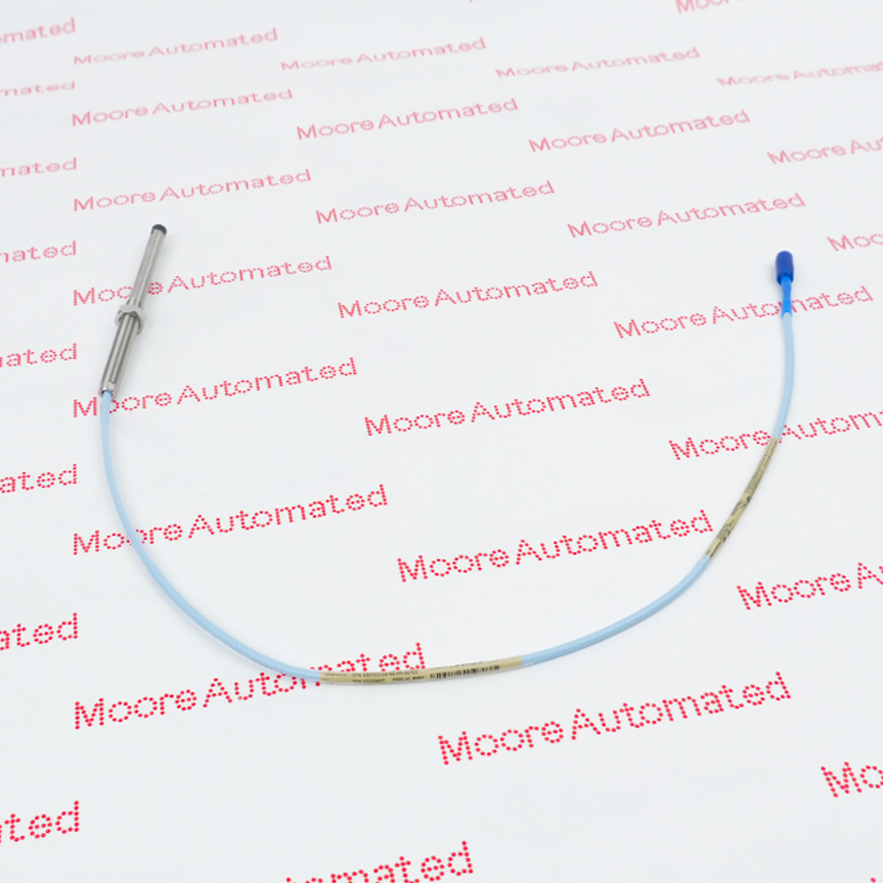
330101-00-70-10-02-05 is a Bently Nevada 3300 XL 8 mm Proximity Probe for the 3300 system. It measures shaft vibration or position without contact in a matched transducer chain. Key specifications: Thread: 3/8-24 UNF-2A; without armor; Unthreaded Length: 0.0 in. Match the full order code and hardware before replacement.
Preserve every option block of 330101-00-70-10-02-05. Retained facts: Thread: 3/8-24 UNF-2A; without armor; Unthreaded Length: 0.0 in; Overall Case Length: 7.0 in. Mechanical length, thread, cable/connector and approval suffixes are part of the exact probe identity.
Match probe family, electrical length, extension cable and Proximitor Sensor. Confirm target material, available travel, nearby probe spacing and mounting geometry before exchange.
Set the operating gap from live bias voltage, support the cable above its bend limit and verify runout, vibration or position response against the commissioning baseline.
Verify that the supplied item is marked 330101-00-70-10-02-05 and that its 3300 xl 8 mm proximity probe, connectors, mounting geometry and printed suffixes agree with the approved record.
Key retained facts: Thread: 3/8-24 UNF-2A; without armor; Unthreaded Length: 0.0 in; Overall Case Length: 7.0 in.
For 330101-00-70-10-02-05, record the connected 3300 system hardware, receiving position, cable or terminal arrangement and configured measurement function.
Review revision, approval, calibration, gap and test requirements before substitution or commissioning.
Confirm the current OEM lifecycle stage for 330101-00-70-10-02-05 at quotation. The supplied 3300 xl 8 mm proximity probe is matched by its complete order code, modification marking, condition and included assemblies.
Any alternative is proposed only after the installed 3300 system, connected signal chain, mechanical fit and commissioning requirements have been reviewed.

Registered Address: 32D Floor Guomao Building, No.388, Hubin South Road, Siming District, Xiamen,Fujian, China
MooreAutomated.com is the official website and primary online platform operated by Moore Automation Limited. The website provides information about the company’s industrial automation parts sourcing services, product coverage and customer support. Moore Automation Limited operates as an independent supplier and is not an authorized distributor or representative of the manufacturers displayed on this website unless expressly stated.