

Registered Address: 32D Floor Guomao Building, No.388, Hubin South Road, Siming District, Xiamen,Fujian, China
ISO 9001:2015 Certified
Our quality management system covers sourcing,testing and dispatch


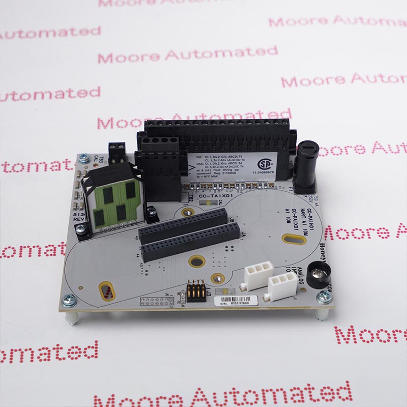
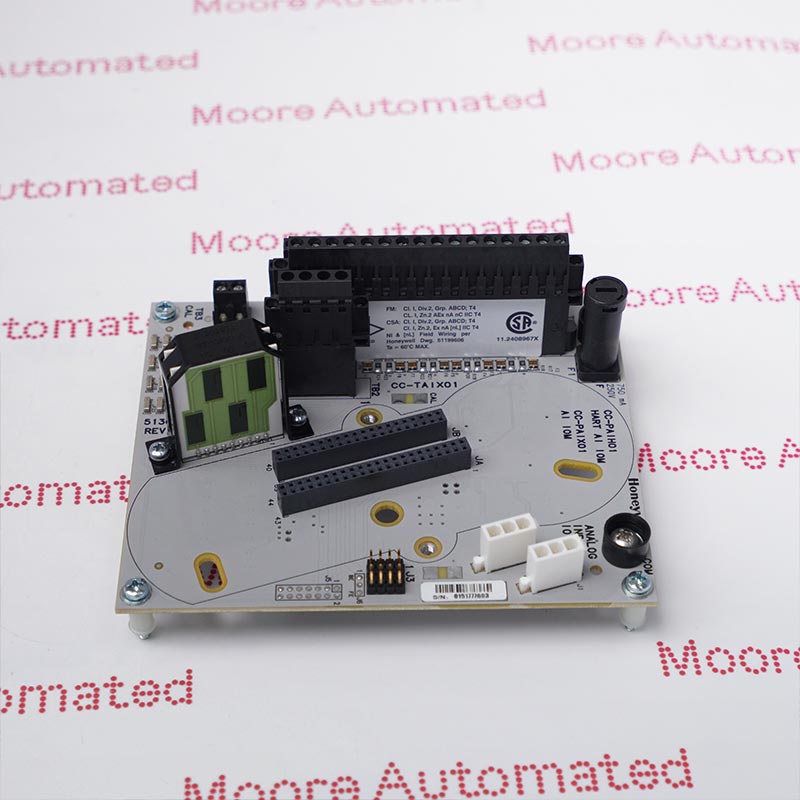
Honeywell identifies CC-TSV211 as the redundant 18-inch IOTA for the CC-PSV201 servo valve positioner module in Series C turbomachinery I/O. The manufacturer table describes a two-valve SVPM assembly with servo output and LVDT/analog feedback options. The IOTA is termination hardware, not the active positioning electronics. Verify the additional 51306665-175 marking and full assembly design before replacement.
Honeywell's October 2019 Experion Series C Turbomachinery I/O Specification lists CC-TSV211 in its IOTA column for CC-PSV201. The IOTA is labeled redundant, 18 inches nominal, and the description identifies a two-valve Servo Valve Positioner Module assembly. Its field connectors and termination arrangement are part of a turbomachinery control installation, where wiring and feedback configuration must match the approved drawings. The two-valve count is an assembly description, not a claim that an unpopulated CC-TSV211 can position valves by itself.
The detailed Honeywell SVPM table includes servo current ranges, LVDT excitation and feedback, analog I/O and digital-input values for the configured CC-PSV201/CC-TSV211 system. These ratings cannot be copied as independent electronics specifications for the bare IOTA. The reviewed PDF also does not map the website's extra 51306665-175 number. Obtain the supplied-unit label and manufacturer parts record, then check the installed positioner module, redundancy arrangement, terminal mapping, valve coils, feedback sensors and safety procedure. Before authorized replacement, preserve configuration and baseline diagnostics; afterward verify termination integrity and all affected positioning and feedback functions under the site's approved turbomachinery test plan.
Honeywell's model table places CC-TSV211 in the IOTA column beside CC-PSV201, the Servo Valve Positioner Module. It identifies an eighteen-inch redundant assembly for two valves. This is termination hardware rather than a complete control processor or active servo electronics. Confirm the exact physical model and additional 51306665-175 marking; the reviewed manufacturer PDF does not associate that number with the model.
The SVPM specification gives numerous current-output, LVDT feedback, analog and digital signal limits for the configured module and IOTA. Those are valid only for the correctly assembled and configured system, not proof that a loose CC-TSV211 independently generates current or digitizes feedback. Check the companion CC-PSV201 electronics, selected valve coils, feedback transducers and wiring against the OEM table and approved turbomachinery design.
Honeywell lists CC-TSV211 as the redundant eighteen-inch SVPM IOTA. Physical size alone does not establish compatibility with another Series C termination or a different controller release. Record both sides of the installed redundancy arrangement, terminal numbers, cable routing and baseline diagnostics. Any exchange in a valve-positioning system should follow the manufacturer's procedure and site risk controls, then be proven through authorized functional testing before service release.
Verify CC-TSV211 on the supplied IOTA and confirm the additional 51306665-175 marking with Honeywell records. Match the installed CC-PSV201 positioning module, 18-inch redundant cabinet position, terminal blocks, valve-coil circuits, LVDT or analog feedback and the approved system release. Use the manufacturer SVPM table for assembled signal limits, but do not treat those as independent active ratings for the unpopulated termination assembly.
Capture positioner configuration, valve and feedback wiring, redundancy state and baseline diagnostics before any authorized work. Follow turbomachinery and site safety procedures so a field change cannot unintentionally move a valve or disrupt a protective function. Restore the verified IOTA, companion electronics and conductors according to the approved drawing. Then check mechanical fit, terminal integrity, both redundant paths and the affected servo-output and feedback functions through a controlled acceptance test.





Registered Address: 32D Floor Guomao Building, No.388, Hubin South Road, Siming District, Xiamen,Fujian, China
MooreAutomated.com is the official website and primary online platform operated by Moore Automation Limited. The website provides information about the company’s industrial automation parts sourcing services, product coverage and customer support. Moore Automation Limited operates as an independent supplier and is not an authorized distributor or representative of the manufacturers displayed on this website unless expressly stated.