

Registered Address: 32D Floor Guomao Building, No.388, Hubin South Road, Siming District, Xiamen,Fujian, China
ISO 9001:2015 Certified
Our quality management system covers sourcing,testing and dispatch
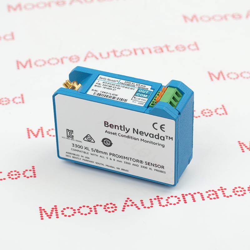
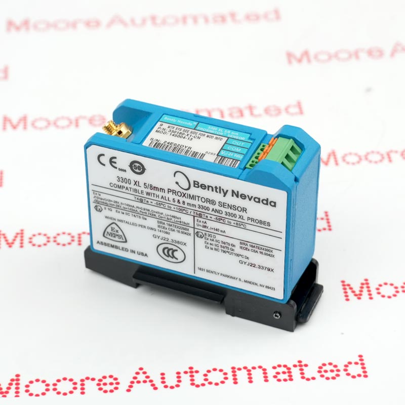
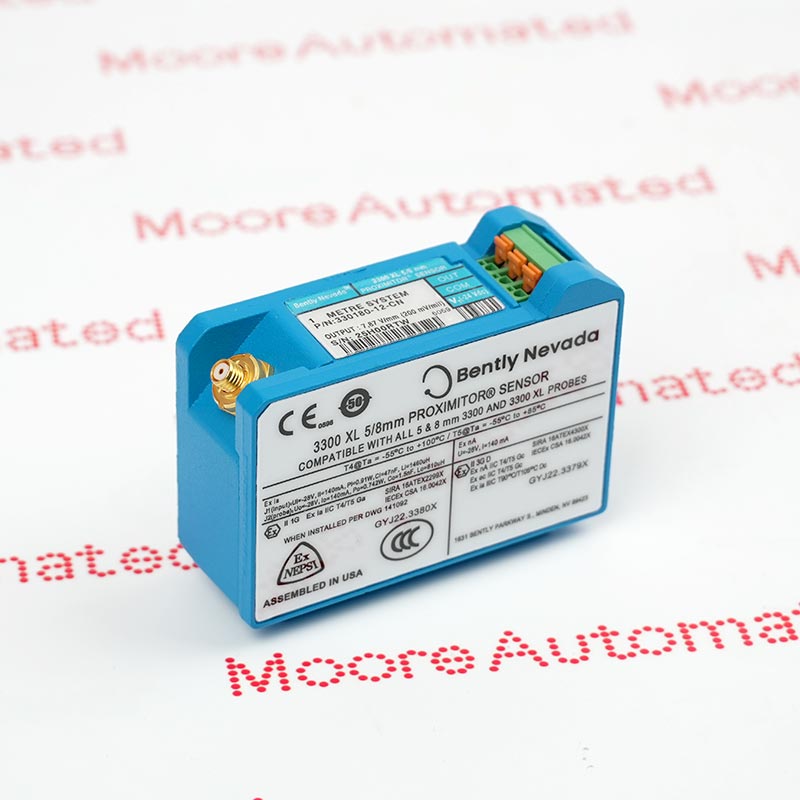
The Bently Nevada 330180-X1-05 MOD:145193-15 is a highly specialized 3300 XL 5/8mm proximity sensor. It is the core component of the Bently Nevada 3300 XL proximity sensor system, converting non-contact eddy current signals from a proximity probe into real-time telemetry data of mechanical vibration, position, or velocity.
Its unique MOD:145193-15 (modified version) is a special custom modification code. It indicates internal electrical calibration for the nonlinear response of specific non-standard target materials (such as special steels or alloys), or hardware tuning for specific cable impedance matching and output dynamic range (such as high frequency or deep water, extremely low temperatures, and other specific operating conditions). This allows for complete interchangeability with probes and extension cables and enables precise transmission of a stable 7.87 V/mm (200 mV/mil) differential voltage signal to the 3500 rack-mounted monitoring system.


Registered Address: 32D Floor Guomao Building, No.388, Hubin South Road, Siming District, Xiamen,Fujian, China
MooreAutomated.com is the official website and primary online platform operated by Moore Automation Limited. The website provides information about the company’s industrial automation parts sourcing services, product coverage and customer support. Moore Automation Limited operates as an independent supplier and is not an authorized distributor or representative of the manufacturers displayed on this website unless expressly stated.