Overview
Manuals
Principle
Functional
Installation
Features:
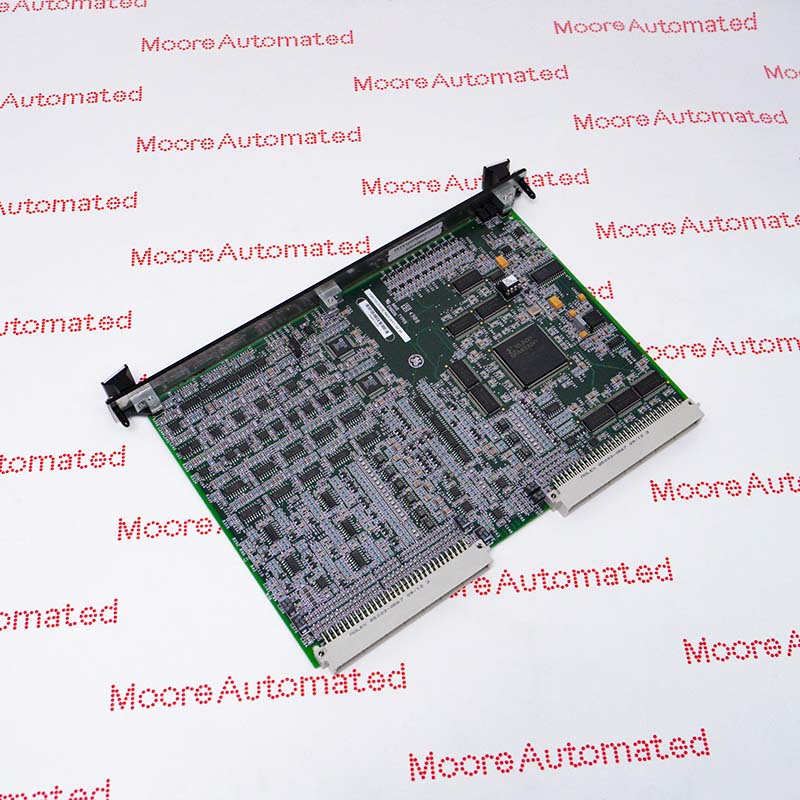
- GE Gas Exciter ISBus Board EX2100 Excitation Control
- Mark VIe & Mark VIeS Control Systems
- Mark VI IS200 Series produced by General Electric
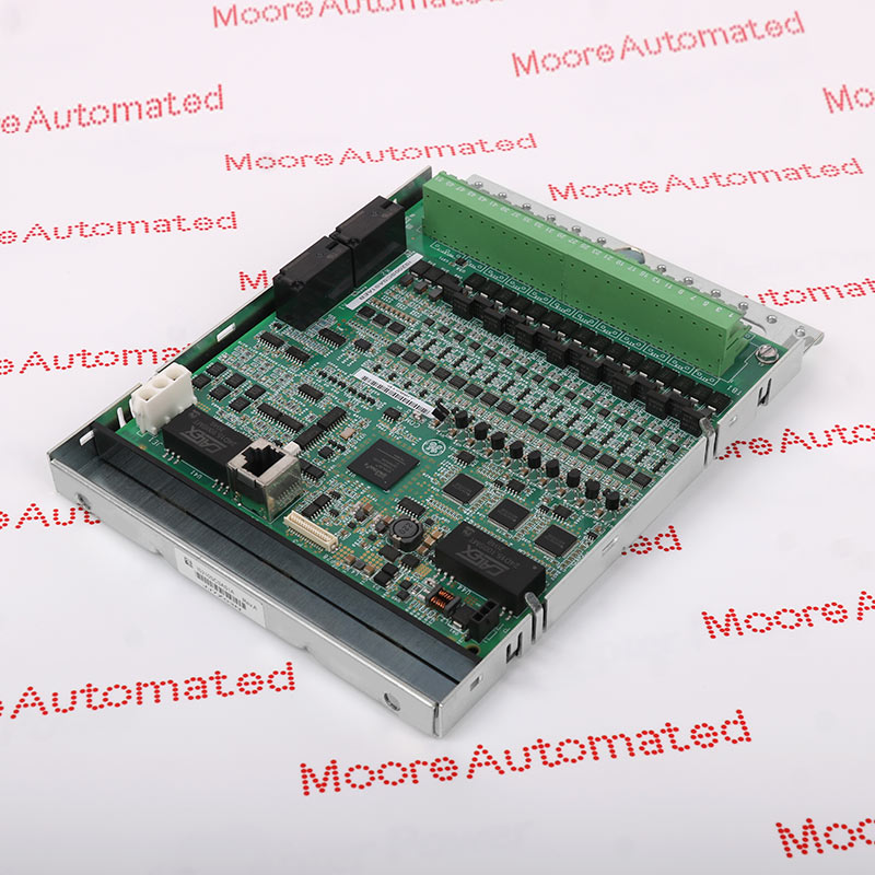
High-performance control processor module designed specifically for the Mark VIe distributed control system platform. Its primary functions are executing control logic, sequential management, and real-time data processing, making it suitable for industrial automation and power generation applications. As the central processing unit in the control architecture, the module coordinates communication between I/O modules, field devices, and monitoring systems to ensure stable and deterministic system operation.
It can handle critical tasks such as signal processing, alarm management, system diagnostics, and fault handling, while maintaining synchronized operation among distributed controllers. Its industrial-grade design allows it to be deployed in demanding environments such as turbines, power plants, and process control facilities where real-time performance and system integrity requirements are extremely high.
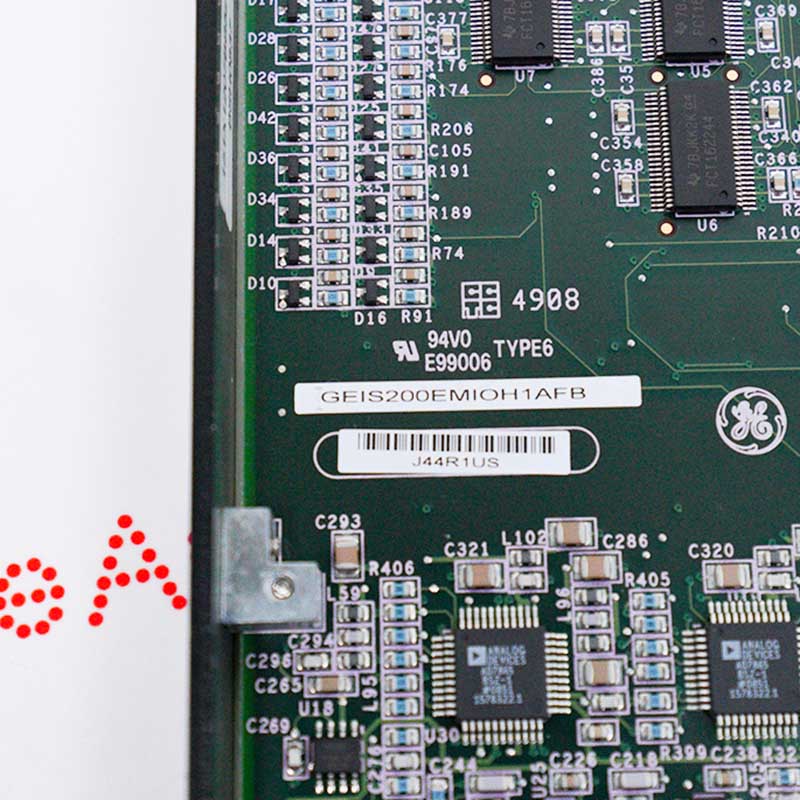
The IS200EMIOH1AFB GENERAL ELECTRIC Exciter Main I/O Board may still be available for purchase and support from Moore Automated Company beyond End-Of-Life (EOL) by the manufacturer (OEM).
GENERAL ELECTRIC IS200EMIOH1AFB Exciter Main I/O Board info(manual), Link
Important Notice: Other accessories, manuals, cables, calibration data, software, etc. are not included with this equipment unless listed in the above stock item description. All prices are shown in USD.
This module receives analog and/or digital input signals from connected sensors or subsystems, performs signal isolation, filtering, and level conversion via onboard circuitry, and then transmits the processed data to the central controller via a high-speed backplane or internal communication bus. Simultaneously, it parses control commands from the main processor and distributes corresponding output signals to relevant field devices or subordinate modules. All of this is achieved through coordinated data exchange, electrical isolation, and embedded firmware logic.
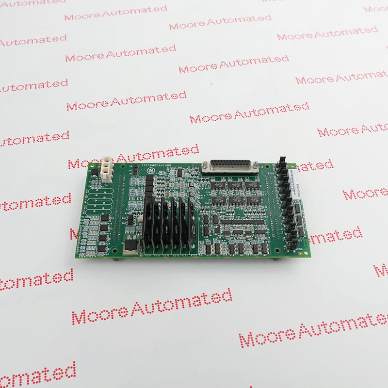
1. Gate Pulse Signal: Receives the gate pulse signal and transmits it to the ESEL board via the backplane, ultimately reaching the EGPA board in the power cabinet.
2. System Protection: When connected to the EXTB board, it controls the relevant EDEX board to start de-excited.
3. Communication: Connector P1 communicates with other control boards via the backplane, while P2 interfaces with I/O signals via the EBKP backplane.
1. Since there are no jumpers, fuses, or manual configuration switches inside the circuit board, proper operation is crucial.
2. Offline Replacement: Before removing the circuit board, ensure the exciter is disabled and check the power supply.
3. Physical Operation: Loosen the retaining screws, use the pop-out latches to lift the module, and then pull it out of the rack with both hands.